Land Cruiser URJ200 URJ202 GRJ200 VDJ200 - CRUISE CONTROL
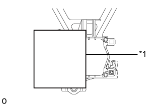
MILLIMETER WAVE RADAR SENSOR - INSTALLATION
| 1. INSTALL MILLIMETER WAVE RADAR SENSOR ASSEMBLY |
Temporarily install the millimeter wave radar sensor assembly with the 3 bolts.
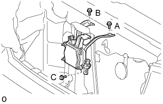
Tighten the 3 bolts in alphabetical order.
- Torque:
- 5.5 N*m{ 56 kgf*cm, 49 in.*lbf}
Connect the sensor connector.
- NOTICE:
- Do not use a sensor which has been dropped or subjected to any strong shocks.
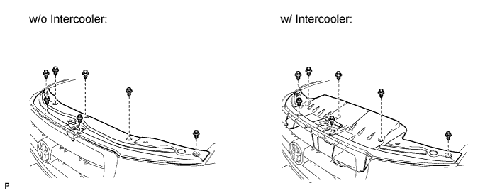
| 2. INSTALL RADIATOR GRILLE ASSEMBLY |
w/ Wide View Front Monitor System:
Connect the connector.
Attach the 2 clips and 8 claws to install the radiator grille assembly.
Install the 3 screws.
| 3. INSTALL UPPER RADIATOR SUPPORT SEAL |
Install the radiator support seal with the 7 clips.
| 4. ADJUST MILLIMETER WAVE RADAR SENSOR ASSEMBLY |

- NOTICE:
| *1 | Approx. 10 m |
| *2 | Approx. 14 m |
Before adjusting, perform the following:
Remove all cargo from the inside of the vehicle.
Adjust the tire pressure to the specified value(s).
Adjust the vehicle's height to the standard height.
Adjust the vertical direction.
Remove any dust and oil from the level rack of the millimeter wave radar sensor assembly.

Set a level for use with the sensor in the center of the level rack of the millimeter wave radar sensor assembly.
| *1 | Level |

Using a screwdriver, adjust the sensor by turning the vertical adjusting bolt of the millimeter wave radar sensor assembly (bolt A) until the air bubble is centered on the red line of the level as shown in the illustration.
- Standard:
- 0.2° upward
- HINT:
- The adjustable range within the red frame of the level is +/-0.2°.
| Vertical adjustment | Upward direction: Turn bolt A in minus direction Downward direction: Turn bolt A in plus direction | For 1 complete turn of screwdriver, sensor moves about 0.12° |
| *1 | Level |
| *2 | Air Bubble |
| *3 | Bolt A |
| *a | FR |
| *b | LH |
| *c | Screwdriver Insertion Hole |

Adjust SST (reflector) height.
Adjust SST (reflector) so that the center of SST (reflector) is the same height as the millimeter wave radar sensor assembly.
- SST
- 09870-60000(09870-60010)
09870-60040
| *1 | Millimeter Wave Radar Sensor |
Place SST (reflector).
Hang a pointed weight from the center of the front and rear bumpers of the vehicle (center of the emblem) and accurately mark the center points on the ground.
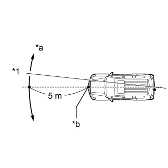
Mark a point 5 m (16.4 ft.) in front of the vehicle on the line that connects the front and rear center point marks.
- HINT:
- Affix one end of a string to the rear center point mark and extend the string 5 m (16.4 ft.) from the front of the vehicle. Move the other end of the string left and right to align the string with the front center point mark and make a straight line.
| *1 | String |
| *a | Adjust Center By Moving String To Right And Left |
| *b | Extend String Through Front Center Mark |
Place SST at a position 12 mm (0.472 in.) from the marked position, to the right of the vehicle.
- NOTICE:
- Perform the operation as precisely as possible.
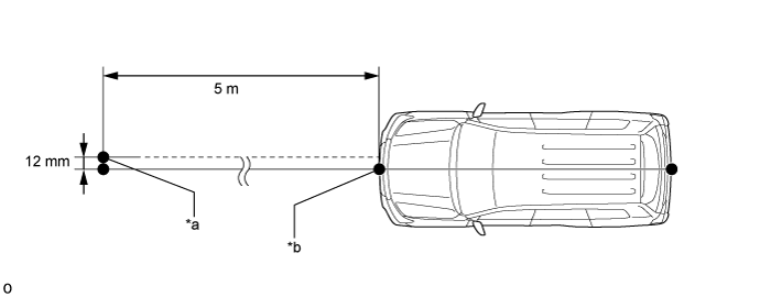
| *a | Reflector (SST) Placement Point | *b | Millimeter Wave Radar Sensor Position |
Adjust the beam axis.
Connect the intelligent tester to the DLC3.
Turn the engine switch on (IG).
Turn the intelligent tester main switch ON, and turn the cruise control main switch ON.
Select "Radar Cruise" from the display screen.
- HINT:
- A buzzer will sound for 1 second.
Select "Utility" from the display screen.
Select "Beam Axis Adjustment" from the display screen.
Follow the tester display, and continue with the adjustment.
Intelligent tester
- NOTICE:
Check the following items on the laser cruise divergence data screen.
- CAUTION:
- While using the intelligent tester's beam axis adjustment mode, the actual direction and angle of the radar sensor may be different from the intelligent tester's data. In such a case, the deviation is displayed on the combination meter's multi-information display.
- HINT:
- HINT:
- If the distance is 0 m (0 ft.), the sensor cannot detect the target. Reconfirm that there is no metal in the specified area in front of the vehicle (refer to the NOTICE at the beginning of this adjustment procedure).
Adjust the horizontal direction.
Read the current amount of angle deviation.
- Standard:
- 0° (Both left and right)

Based on the results of the beam axis deviation measurement, using a screwdriver, adjust the sensor by turning the horizontal adjusting bolt of the millimeter wave radar sensor assembly (bolt B).
| Horizontal adjustment | Right direction: Turn bolt B in plus direction Left direction: Turn bolt B in minus direction | For 1 complete turn of screwdriver, sensor moves about 0.07° |
- NOTICE:
- If it is difficult to reach a value of 0°, it is possible that the sensor is targeting an object other than SST. Reconfirm that there are no reflective objects in the surrounding area.
| *1 | Bolt B |
| *a | Screwdriver Insertion Hole |
Because the driving learned value will be reset, cover the left half of the sensor with aluminum foil or equivalent (a metal material that blocks electric waves) for a period of approximately 10 seconds.
- NOTICE:
- At this time, leave SST in place and make sure there are no objects between the right half of the sensor and the reflector.
- HINT:
- When the value is reset, the buzzer will sound for 10 seconds, a distance value between 0 and 6.3° and a right side value between 0 and 6.3 m (20.7 ft.) will be displayed on the screen.
| *1 | Aluminum foil |
Continue the procedure according to the display to complete the beam axis adjustment.
Disconnect the intelligent tester from the vehicle.
Reconfirm the vertical direction.
Set a level for use with the sensor in the center of the level rack of the millimeter wave radar sensor assembly.
| *1 | Level |
Using a screwdriver, adjust the sensor by turning the vertical adjusting bolt of the millimeter wave radar sensor assembly (bolt A) until the air bubble is centered on the red line of the level as shown in the illustration.
- Standard:
- 0.2° upward
- HINT:
- The adjustable range within the red frame of the level is +/-0.2°.
| Vertical adjustment | Upward direction: Turn bolt A in minus direction Downward direction: Turn bolt A in plus direction | For 1 complete turn of screwdriver, sensor moves about 0.12° |
| *1 | Level |
| *2 | Air Bubble |
| *3 | Bolt A |
| *a | FR |
| *b | LH |
| *c | Screwdriver Insertion Hole |
| 5. PERFORM DRIVE TEST |
Perform the drive test.
- NOTICE:
Drive at 30 km/h (19 mph) on a straight road with good visibility while staying in the center of the lane.
- NOTICE:
- Because the pre-crash safety system may activate under the following conditions, avoid conditions like these when performing the test.
On a straight road, when passing an oncoming vehicle with no danger of collision, check that the master warning does not illuminate and that the buzzer does not sound. At the same time, check that "BRAKE!" is not displayed on the display in the combination meter.
If "BRAKE!" is displayed, perform the millimeter wave radar sensor assembly adjustment again.
- HINT: