Land Cruiser URJ200 URJ202 GRJ200 VDJ200 - 3UR-FE INTAKE / EXHAUST
INTAKE MANIFOLD - INSTALLATION
| 1. INSTALL WIRE HARNESS CLAMP BRACKET |
Install the 2 wire harness clamp brackets with the 2 bolts.
- Torque:
- 8.0 N*m{ 82 kgf*cm, 71 in.*lbf}
| 2. INSTALL PURGE VSV |
Connect the purge line hose to the intake manifold.
Install the purge VSV to the intake manifold with the bolt.
- Torque:
- 21 N*m{ 214 kgf*cm, 15 ft.*lbf}
| 3. INSTALL VACUUM SWITCHING VALVE ASSEMBLY (for ACIS) |
Install the vacuum switching valve to the intake manifold with the bolt.
- Torque:
- 9.0 N*m{ 92 kgf*cm, 80 in.*lbf}
Connect the 2 vacuum hoses to the vacuum switching valve.
| 4. INSTALL THROTTLE BODY ASSEMBLY |

Align the protrusion of a new gasket with the groove of the intake manifold, and install the gasket.
| *1 | Groove |
| *2 | Protrusion |
| *a | Surge Tank Side |
| *b | Throttle Body Side |
Install the throttle body with the 4 bolts.
- Torque:
- 10 N*m{ 102 kgf*cm, 7 ft.*lbf}
| 5. INSTALL NO. 2 V-BANK COVER BRACKET SUB-ASSEMBLY |
Install the bracket with the bolt.
- Torque:
- 10 N*m{ 102 kgf*cm, 7 ft.*lbf}
| 6. INSTALL V-BANK COVER BOLT |
Install the cover bolt to the intake manifold.
- Torque:
- 10 N*m{ 102 kgf*cm, 7 ft.*lbf}
| 7. INSTALL NO. 1 V-BANK COVER BRACKET |
Install the bracket with the 2 bolts.
- Torque:
- 10 N*m{ 102 kgf*cm, 7 ft.*lbf}
| 8. INSTALL VENTILATION HOSE ASSEMBLY |

Install the ventilation hose to the intake manifold with the 2 bolts.
- Torque:
- for bolt A:
- 21 N*m{ 214 kgf*cm, 15 ft.*lbf}
- for bolt B:
- 10 N*m{ 102 kgf*cm, 7 ft.*lbf}
| 9. INSTALL INTAKE MANIFOLD |

Place 2 new gaskets on the intake manifold.
| *1 | Gasket |
Place the intake manifold on the cylinder head.
Install and uniformly tighten the 8 bolts and 2 nuts in several steps.
- Torque:
- 21 N*m{ 214 kgf*cm, 15 ft.*lbf}
Install the wire bracket to the intake manifold with the bolt.
- Torque:
- 8.0 N*m{ 82 kgf*cm, 71 in.*lbf}
Connect the 3 wire clamps to the 3 wire brackets.
Install the No. 3 engine cover.
Install the No. 1 engine cover sub-assembly.
Connect the purge VSV connector.
Connect the purge line hose to the purge VSV.
Connect the vacuum switching valve connector (for ACIS).
Connect the No. 1 ventilation hose.
Connect the 2 water by-pass hoses.
Connect the throttle body connector.
Connect the ventilation hose to the ventilation pipe of the cylinder head cover LH and RH.
| 10. INSTALL AIR CLEANER HOSE ASSEMBLY |

Install the air cleaner hose so that the protrusion of the air cleaner cap aligns with the groove of the hose as shown in the illustration.
| *1 | Groove |
| *2 | Protrusion |
Tighten the 2 clamps.
- Torque:
- 2.5 N*m{ 25 kgf*cm, 22 in.*lbf}
Connect the vacuum hose.
Connect the No. 2 ventilation hose.
| 11. ADD ENGINE COOLANT |
Add engine coolant.
- Standard Capacity:
Item Specified Condition with rear heater 16.2 liters (17.1 US qts, 14.3 Imp. qts) without rear heater 13.4 liters (14.2 US qts, 11.8 Imp. qts)
- NOTICE:
- Do not substitute plain water for engine coolant.
- HINT:
- TOYOTA vehicles are filled with TOYOTA SLLC at the factory. In order to avoid damage to the engine cooling system and other technical problems, only use TOYOTA SLLC or similar high quality ethylene glycol based non-silicate, non-amine, non-nitrite, non-borate coolant with long-life hybrid organic acid technology (coolant with long-life hybrid organic acid technology consists of a combination of low phosphates and organic acids).
Slowly pour coolant into the radiator reservoir until it reaches the F line.
Install the reservoir cap.
Press the No. 1 and No. 2 radiator hoses several times by hand, and then check the coolant level. If the coolant level is low, add coolant.
Install the radiator cap.
Start the engine and warm it up until the thermostat opens.
- HINT:
- The thermostat opening timing can be confirmed by pressing the radiator inlet hose by hand, and checking when the engine coolant starts to flow inside the hose.
Maintain the engine speed at 2000 to 2500 rpm.
- NOTICE:
Press the No. 1 and No. 2 radiator hoses several times by hand to bleed air.
- CAUTION:
Stop the engine, and wait until the engine coolant cools down to ambient temperature.
- CAUTION:
- Do not remove the radiator cap while the engine and radiator are still hot. Pressurized, hot engine coolant and steam may be released and cause serious burns.
Check that the coolant level is between the F and L lines.
If the coolant level is below the L line, repeat all of the procedures above.
If the coolant level is above the F line, drain coolant so that the coolant level is between the F and L lines.
| 12. INSPECT FOR COOLANT LEAK |
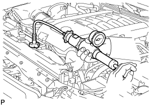
- CAUTION:
- Do not remove the radiator cap while the engine and radiator are still hot. Pressurized, hot engine coolant and steam may be released and cause serious burns.
Fill the radiator with coolant and attach a radiator cap tester.
Warm up the engine.
Using the radiator cap tester, increase the pressure inside the radiator to 123 kPa (1.3 kgf/cm2, 18 psi), and check that the pressure does not drop.
If the pressure drops, check the hoses, radiator and water pump for leaks. If no external leaks are found, check the heater core, cylinder block and head.
| 13. INSTALL V-BANK COVER SUB-ASSEMBLY |
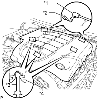
Attach the 2 V-bank cover hooks to the bracket. Then align the 3 V-bank cover grommets with the 3 pins, and press down on the V-bank cover to attach the pins.
| *1 | Bracket |
| *2 | Hook |
| *3 | Pin |
| *4 | Grommet |
| 14. INSTALL NO. 1 ENGINE UNDER COVER SUB-ASSEMBLY |
Install the No. 1 engine under cover with the 10 bolts.
- Torque:
- 29 N*m{ 296 kgf*cm, 21 ft.*lbf}
| 15. INSTALL FRONT FENDER SPLASH SHIELD SUB-ASSEMBLY LH |
Push in the clip to install the front fender splash shield sub-assembly LH.
Install the 3 bolts and screw.
| 16. INSTALL FRONT FENDER SPLASH SHIELD SUB-ASSEMBLY RH |
Push in the clip to install the front fender splash shield sub-assembly RH.
Install the 3 bolts and 2 screws.
| 17. INSTALL COWL TOP VENTILATOR LOUVER SUB-ASSEMBLY |
()
| 18. CONNECT CABLE TO NEGATIVE BATTERY TERMINAL |
- NOTICE:
- When disconnecting the cable, some systems need to be initialized after the cable is reconnected ().
| 19. CHECK THROTTLE BODY ASSEMBLY |
Check the throttle control motor operating sounds.
Turn the engine switch on (IG).
When depressing the accelerator pedal, check the operating sound of the running motor. Make sure that no friction noises are emitted from the motor. If friction noise exists, replace the throttle body.
Check the throttle position sensor.
Connect the intelligent tester to the DLC3.
Turn the engine switch on (IG).
Turn the intelligent tester main switch on.
Enter the following menus: Powertrain / Engine and ECT / Data List / All Data / Throttle Sensor Volt %.
Depress the accelerator pedal. When the throttle valve is fully opened, check that the value of "Throttle Sensor Volt %" is within the specification.
- Standard throttle valve opening percentage:
- 60% or more
- HINT:
- When checking the standard throttle valve opening percentage, the shift lever should be in N.
If the percentage is less than 60%, replace the throttle body.