Land Cruiser URJ200 URJ202 GRJ200 VDJ200 - 1VD-FTV FUEL
FUEL TEMPERATURE SENSOR - INSTALLATION
| 1. INSTALL FUEL TEMPERATURE SENSOR |
- NOTICE:
- If the fuel temperature sensor is dropped, replace it with a new one.
Apply a light coat of engine oil to a new O-ring.
Install the O-ring to the sensor.
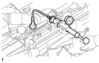
Using SST, install the fuel temperature sensor.
- SST
- 09817-33190
- Torque:
- 22 N*m{ 224 kgf*cm, 16 ft.*lbf}

Connect the fuel temperature sensor connector.
| 2. INSTALL NO. 1 AIR CLEANER PIPE SUB-ASSEMBLY |
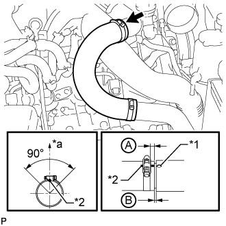
Connect the No. 1 air cleaner pipe to the No. 1 intake air connector pipe.
Install the pipe with the bolt.
- Torque:
- 21 N*m{ 214 kgf*cm, 15 ft.*lbf}
Tighten the hose clamp.
- Torque:
- 6.3 N*m{ 64 kgf*cm, 56 in.*lbf}
| 3. INSTALL HEATER WATER PIPE SUB-ASSEMBLY (w/ Viscous Heater) |
Connect the 4 water hose ends, and install the water pipe with the 4 bolts.
- Torque:
- 9.8 N*m{ 100 kgf*cm, 87 in.*lbf}
| 4. INSTALL INTAKE AIR CONNECTOR |
Connect the intake air connector to the No. 1 and No. 2 air cleaner pipes.
Install the connector with the 2 bolts.
- Torque:
- 21 N*m{ 214 kgf*cm, 15 ft.*lbf}
Tighten the 2 hose clamps.
- Torque:
- 6.3 N*m{ 64 kgf*cm, 56 in.*lbf}
Attach the 3 wire harness clamps.
w/o Viscous Heater:
Connect the connector to the water temperature sensor.
w/ Viscous Heater:
Connect the 2 connectors to the water temperature sensor and viscous with magnet clutch heater.
| 5. TEMPORARILY INSTALL NO. 1 AIR CLEANER HOSE |
Temporarily install the air cleaner hose to the intake air connector.
| 6. INSTALL AIR CLEANER CAP SUB-ASSEMBLY |
Connect the air cleaner cap to the air cleaner hose, and install the air cleaner cap with the 4 clamps.
Connect the mass air flow meter connector and attach the wire harness clamp to the air cleaner cap.
Attach the wire harness clamp.
Align the protrusion of the air cleaner cap and the concave portion of the air cleaner hose.
Tighten the 2 hose clamps.
- Torque:
- 2.5 N*m{ 25 kgf*cm, 22 in.*lbf}
| 7. CONNECT WATER HOSE SUB-ASSEMBLY (w/ Viscous Heater) |
| 8. INSTALL NO. 2 COOL AIR INLET (w/o Intercooler) |

Install a new gasket to the air tube LH.
| *1 | Protrusion |
| *a | Front |
| *b | LH Side |
- HINT:
- Install the gasket with the protrusion facing as shown in the illustration.
Install the No. 2 cool air inlet with the 3 nuts and bolt.
- Torque:
- 21 N*m{ 214 kgf*cm, 15 ft.*lbf}

Connect the No. 2 air hose to the No. 2 cool air inlet.
| *1 | Protrusion |
| *2 | Paint Mark |
| *a | Top |
Tighten the No. 2 air hose clamp.
- Torque:
- 6.3 N*m{ 64 kgf*cm, 56 in.*lbf}
- HINT:
| 9. INSTALL NO. 1 COOL AIR INLET (w/o Intercooler) |

Install a new gasket to the air tube RH.
| *1 | Protrusion |
| *a | Front |
| *b | RH Side |
- HINT:
- Install the gasket with the protrusion facing as shown in the illustration.
Install the No. 1 cool air inlet with the 3 nuts and bolt.
- Torque:
- 21 N*m{ 214 kgf*cm, 15 ft.*lbf}
Connect the vacuum hose, intake air temperature sensor connector and turbo pressure sensor connector.
Connect the No. 1 air hose to the No. 1 cool air inlet.
| *1 | Protrusion |
| *2 | Paint Mark |
| *a | Top |
Tighten the No. 1 air hose clamp.
- Torque:
- 6.3 N*m{ 64 kgf*cm, 56 in.*lbf}
- HINT:
| 10. INSTALL INTERCOOLER ASSEMBLY (w/ Intercooler) |
()
| 11. CONNECT CABLE TO NEGATIVE BATTERY TERMINAL |
- NOTICE:
- After turning the ignition switch off, waiting time may be required before disconnecting the cable from the battery terminal. Therefore, make sure to read the disconnecting the cable from the battery terminal notice before proceeding with work ().
| 12. ADD ENGINE COOLANT (w/ Viscous Heater) |

Remove the engine air bleed cap.

Connect a clear hose to the engine air bleed pipe.
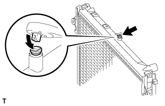
Using a wrench, remove the vent plug.

Fill the radiator with TOYOTA SLLC to the radiator reservoir filler neck.
- HINT:
- Pour TOYOTA SLLC until it spills out of the engine air bleed pipe.
- Standard Capacity (for Automatic Transmission):
Item Specified Condition Front heater only 14.8 liters (15.6 US qts, 13.0 Imp. qts) Front heater and rear heater 17.6 liters (18.6 US qts, 15.5 Imp. qts) Front heater with viscous heater 15.2 liters (16.1 US qts, 13.4 Imp. qts) Front heater and rear heater with viscous heater 18.0 liters (19.0 US qts, 15.4 Imp. qts)
- Standard capacity (for Manual Transmission):
- 15.4 liters (16.3 US qts, 13.5 Imp. qts)
- NOTICE:
- Do not substitute plain water for engine coolant.
- HINT:
- TOYOTA vehicles are filled with TOYOTA SLLC at the factory. In order to avoid damage to the engine cooling system and other technical problems, only use TOYOTA SLLC or similar high quality ethylene glycol based non-silicate, non-amine, non-nitrite, non-borate coolant with long-life hybrid organic acid technology (coolant with long-life hybrid organic acid technology consists of a combination of low phosphates and organic acids).
Install the vent plug.
- Torque:
- 2.0 N*m{ 20 kgf*cm, 18 in.*lbf}
- NOTICE:
- Do not tighten the plug to 5.0 N*m (51 kgf*cm, 44 in.*lbf) or more, as the plug will be damaged.
Disconnect the clear hose from the engine air bleed pipe.
Install the engine air bleed cap when coolant comes out.
Install the radiator reservoir cap.
Start the engine.
- NOTICE:
- Immediately after starting the engine, if the radiator reservoir does not have any coolant, perform the following: 1) stop the engine, 2) wait until the coolant has cooled down, and 3) add coolant until the coolant is filled to the FULL line.
Maintain an engine speed of 3000 rpm for approximately 10 minutes so that the thermostat opens and air bleeding is performed.
- CAUTION:
- NOTICE:
- HINT:
- The thermostat opening timing can be confirmed by pressing the No. 2 radiator hose by hand, and checking when the engine coolant starts to flow inside the hose.
Stop the engine, and wait until the engine coolant cools down to ambient temperature.
- CAUTION:
- Do not remove the radiator reservoir cap while the engine and radiator are still hot. Pressurized, hot engine coolant and steam may be released and cause serious burns.

Check that the coolant level is between the FULL and LOW lines.
If the coolant level is above the FULL line, drain coolant so that the coolant level is between the FULL and LOW lines.
| 13. INSPECT FOR COOLANT LEAK (w/ Viscous Heater) |
- CAUTION:
- Do not remove the radiator reservoir cap while the engine and radiator are still hot. Pressurized, hot engine coolant and steam may be released and cause serious burns.
Fill the radiator with coolant and attach a radiator cap tester to the radiator reservoir.
Warm up the engine.
Using the radiator cap tester, increase the pressure inside the radiator to 123 kPa (1.3 kgf/cm2, 17.8 psi), and check that the pressure does not drop.
If the pressure drops, check the hoses, radiator and water pump for leaks.
If no external leaks are found, check the cylinder block and cylinder head.
| 14. INSTALL UPPER RADIATOR SUPPORT SEAL (w/ Viscous Heater) |
Install the upper radiator support seal with the 7 clips.
| 15. INSTALL NO. 1 ENGINE UNDER COVER SUB-ASSEMBLY (w/ Viscous Heater) |
Install the No. 1 engine under cover with the 10 bolts.
- Torque:
- 29 N*m{ 296 kgf*cm, 21 ft.*lbf}
| 16. INSTALL FRONT FENDER SPLASH SHIELD SUB-ASSEMBLY RH (w/ Viscous Heater) |
Install the front fender splash shield RH with the clip, and then install the 3 bolts and 2 screws.
| 17. INSTALL FRONT FENDER SPLASH SHIELD SUB-ASSEMBLY LH (w/ Viscous Heater) |
Install the front fender splash shield LH with the clip, and then install the 3 bolts and screw.