Land Cruiser URJ200 URJ202 GRJ200 VDJ200 - 1UR-FE INTAKE / EXHAUST
EXHAUST MANIFOLD - INSTALLATION
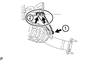
| 1. INSTALL AIR FUEL RATIO SENSOR (for Bank 1 Sensor 1) |
Temporarily install the air fuel ratio sensor to the exhaust manifold LH by hand.

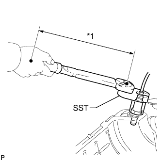
Using SST, tighten the air fuel ratio sensor.
- SST
- 09224-00010
- Torque:
- without SST:
- 44 N*m{ 449 kgf*cm, 32 ft.*lbf}
- with SST:
- 40 N*m{ 408 kgf*cm, 30 ft.*lbf}
| *1 | Fulcrum Length |
- HINT:
| 2. INSTALL AIR FUEL RATIO SENSOR (for Bank 2 Sensor 1) |
Temporarily install the air fuel ratio sensor to the exhaust manifold RH by hand.
Using SST, tighten the air fuel ratio sensor.
- SST
- 09224-00010
- Torque:
- without SST:
- 44 N*m{ 449 kgf*cm, 32 ft.*lbf}
- with SST:
- 40 N*m{ 408 kgf*cm, 30 ft.*lbf}
| *1 | Fulcrum Length |
- HINT:
| 3. INSTALL EXHAUST MANIFOLD ASSEMBLY RH |
w/ Secondary Air Injection System:
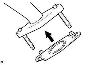
Install a new gasket to the No. 3 air tube.
- HINT:
- Install the gasket with the claws of the gasket facing the tube.
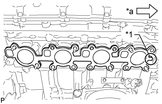
Install a new gasket to the cylinder head.
| *1 | Tab |
| *a | Front |
- HINT:
- Install the gasket with the gasket tab facing toward the front of the engine.
w/ Secondary Air Injection System:

Install the exhaust manifold to the cylinder head with the 7 new nuts labeled A.
- Torque:
- 21 N*m{ 214 kgf*cm, 15 ft.*lbf}
Install the exhaust manifold to the No. 3 air tube with the 2 nuts labeled B.
- Torque:
- 10 N*m{ 102 kgf*cm, 7 ft.*lbf}
w/o Secondary Air Injection System:
Install the exhaust manifold with 7 new nuts.
- Torque:
- 21 N*m{ 214 kgf*cm, 15 ft.*lbf}
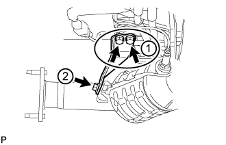
Connect the air fuel ratio sensor connector and attach the wire harness clamp.
| 4. INSTALL NO. 1 EXHAUST MANIFOLD HEAT INSULATOR |
Install the heat insulator with 3 new bolts.
- Torque:
- 10 N*m{ 102 kgf*cm, 7 ft.*lbf}
| 5. INSTALL ENGINE OIL LEVEL DIPSTICK GUIDE |
Apply engine oil to a new O-ring, and then install the O-ring to the engine oil level dipstick guide.
Install the engine oil level dipstick guide with the bolt.
- Torque:
- 10 N*m{ 102 kgf*cm, 7 ft.*lbf}
Attach the engine wire clamp.
Install the engine oil level dipstick.
| 6. INSTALL MANIFOLD STAY |
Temporarily install the manifold stay with the 3 bolts.
Tighten the 3 bolts in the sequence shown in the illustration.
- Torque:
- 40 N*m{ 408 kgf*cm, 30 ft.*lbf}
| 7. INSTALL EXHAUST MANIFOLD ASSEMBLY LH |
w/ Secondary Air Injection System:
Install a new gasket to the No. 4 air tube.
- HINT:
- Install the gasket with the claws of the gasket facing the tube.

Install a new gasket to the cylinder head.
| *1 | Tab |
| *a | Front |
- HINT:
- Install the gasket with the gasket tab facing toward the rear of the engine.
w/ Secondary Air Injection System:

Install the exhaust manifold to the cylinder head with the 7 new nuts labeled A.
- Torque:
- 21 N*m{ 214 kgf*cm, 15 ft.*lbf}
Install the exhaust manifold to the No. 4 air tube with the 2 nuts labeled B.
- Torque:
- 10 N*m{ 102 kgf*cm, 7 ft.*lbf}
w/o Secondary Air Injection System:
Install the exhaust manifold with 7 new nuts.
- Torque:
- 21 N*m{ 214 kgf*cm, 15 ft.*lbf}
Connect the air fuel ratio sensor connector and attach the wire harness clamp.
| 8. INSTALL NO. 2 EXHAUST MANIFOLD HEAT INSULATOR |
Install the heat insulator with 3 new bolts.
- Torque:
- 10 N*m{ 102 kgf*cm, 7 ft.*lbf}
| 9. INSTALL NO. 2 MANIFOLD STAY |
Temporarily install the manifold stay with the 3 bolts.
Tighten the 3 bolts in the sequence shown in the illustration.
- Torque:
- 40 N*m{ 408 kgf*cm, 30 ft.*lbf}
| 10. INSTALL PROPELLER SHAFT HEAT INSULATOR |
Install the propeller shaft heat insulator with the 2 bolts.
- Torque:
- 16 N*m{ 160 kgf*cm, 12 ft.*lbf}
| 11. INSTALL FRONT PROPELLER SHAFT ASSEMBLY |
()
| 12. INSTALL FRONT EXHAUST PIPE ASSEMBLY |
()
| 13. INSPECT FOR EXHAUST GAS LEAK |
If gas is leaking, tighten the areas necessary to stop the leak. Replace damaged parts as necessary.
| 14. INSTALL FRONT FENDER APRON TRIM PACKING C |
Install the front fender apron trim packing C with the 4 clips.
| 15. INSTALL FRONT FENDER APRON TRIM PACKING A |
Install the front fender apron trim packing A with the 3 clips.
| 16. INSTALL FRONT FENDER APRON TRIM PACKING D |
Install the front fender apron trim packing D with the 4 clips.
| 17. INSTALL FRONT FENDER APRON TRIM PACKING B |
w/ KDSS
Install the front fender apron trim packing B with the 3 clips.
w/o KDSS
Install the front fender apron trim packing B with the 4 clips.
| 18. INSTALL NO. 2 ENGINE UNDER COVER |
Install the No. 2 engine under cover with the 2 bolts.
- Torque:
- 29 N*m{ 296 kgf*cm, 21 ft.*lbf}
| 19. INSTALL NO. 1 ENGINE UNDER COVER SUB-ASSEMBLY |
Install the No. 1 engine under cover sub-assembly with the 10 bolts.
- Torque:
- 29 N*m{ 296 kgf*cm, 21 ft.*lbf}
| 20. INSTALL FRONT FENDER SPLASH SHIELD SUB-ASSEMBLY RH |
Push in the clip to install the front fender splash shield sub-assembly RH.
Install the 3 bolts and 2 screws.
| 21. INSTALL FRONT FENDER SPLASH SHIELD SUB-ASSEMBLY LH |
Push in the clip to install the front fender splash shield sub-assembly LH.
Install the 3 bolts and screw.
| 22. INSTALL AIR CLEANER AND HOSE |
Install the air cleaner and hose with the 3 bolts, and then tighten the hose clamp.
- Torque:
- for bolt:
- 5.0 N*m{ 51 kgf*cm, 44 in.*lbf}
- for hose clamp:
- 2.5 N*m{ 25 kgf*cm, 22 in.*lbf}
Attach the clamp and connect the mass air flow meter connector.
Connect the No. 2 PCV hose and No. 1 air hose.
| 23. INSTALL V-BANK COVER SUB-ASSEMBLY |
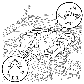
Attach the 2 V-bank cover hooks to the bracket. Then align the 3 V-bank cover grommets with the 3 pins, and press down on the V-bank cover to attach the pins.
| *1 | Grommet |
| *2 | Pin |
| *3 | Hook |
| *4 | Bracket |