Land Cruiser URJ200 URJ202 GRJ200 VDJ200 - 1UR-FE ENGINE MECHANICAL
ENGINE UNIT - REMOVAL
| 1. REMOVE ENGINE WIRE |
| 2. REMOVE FUEL HOSE |
Remove the fuel pipe clamp.
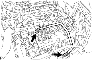
Disconnect the 2 clamps and remove the fuel hose ().
| 3. REMOVE FUEL TUBE SUB-ASSEMBLY |

Remove the 2 bolts and fuel tube ().
| 4. REMOVE AIR SWITCHING VALVE ASSEMBLY (w/ Secondary Air Injection System) |
| 5. REMOVE NO. 4 AIR TUBE (w/ Secondary Air Injection System) |
Remove the bolt and No. 4 air tube.
| 6. REMOVE NO. 3 AIR TUBE (w/ Secondary Air Injection System) |
Remove the bolt and No. 3 air tube.
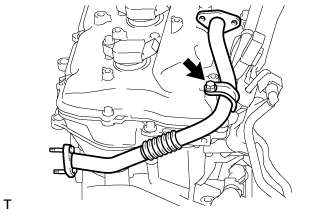
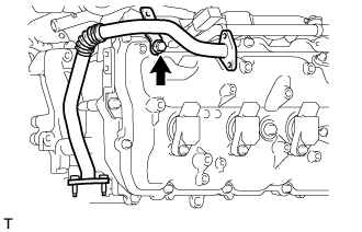
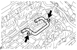
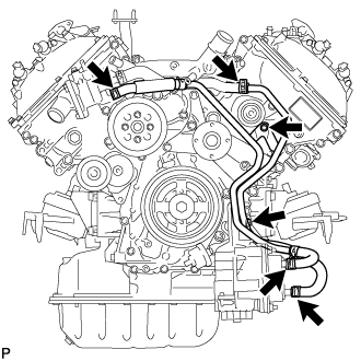
| 7. REMOVE NO. 2 WATER BY-PASS PIPE |
Disconnect the hose and remove the 2 bolts and No. 2 water by-pass pipe.
| 8. REMOVE NO. 8 WATER BY-PASS HOSE |

| 9. DISCONNECT NO. 11 WATER BY-PASS HOSE |

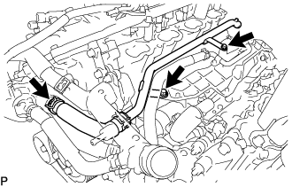
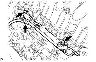
| 10. REMOVE NO. 1 WATER OUTLET PIPE |
Remove the 2 bolts and No. 1 water outlet pipe.
| 11. REMOVE NO. 1 EGR PIPE BRACKET |
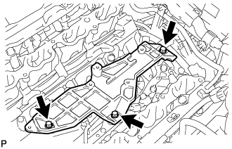
Remove the 3 bolts and No. 1 EGR pipe bracket.
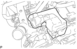
| 12. REMOVE FRONT NO. 1 ENGINE MOUNTING BRACKET RH |

Remove the 4 bolts and front No. 1 engine mounting bracket RH.
| 13. REMOVE FRONT NO. 1 ENGINE MOUNTING BRACKET LH |

Remove the 4 bolts and front No. 1 engine mounting bracket LH.
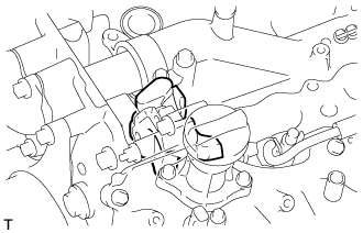
| 14. REMOVE FUEL DELIVERY PIPE SUB-ASSEMBLY |
Disconnect the No. 6 wire harness connector.
Remove the 2 bolts and fuel delivery pipe.
- NOTICE:
- When removing the delivery pipe, hold the pipe by both ends and pull it straight upward.
Remove the 2 delivery pipe spacers and 4 insulators from the intake manifold.
| 15. REMOVE NO. 2 FUEL DELIVERY PIPE SUB-ASSEMBLY |

Disconnect the No. 7 wire harness connector.
Remove the 2 bolts and No. 2 fuel delivery pipe.
- NOTICE:
- When removing the delivery pipe, hold the pipe by both ends and pull it straight upward.
Remove the 2 delivery pipe spacers and 4 insulators from the intake manifold.
| 16. REMOVE NO. 4 ENGINE COVER |

| 17. REMOVE NO. 3 ENGINE COVER |
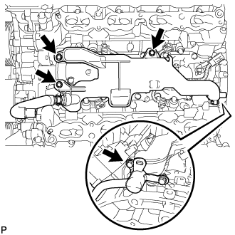
| 18. REMOVE NO. 2 WATER BY-PASS PIPE SUB-ASSEMBLY |
Remove the 2 bolts.
Disconnect the 4 hoses and remove the No. 2 water by-pass pipe.
| 19. REMOVE NO. 1 WATER BY-PASS HOSE |

Remove the No. 1 water by-pass hose.
| 20. REMOVE WATER PUMP PULLEY |
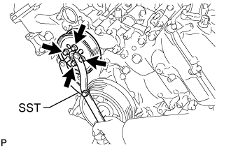
Using SST, hold the water pump pulley.
- SST
- 09960-10010(09962-01000,09963-01000)
Remove the 4 bolts and water pump pulley.
| 21. REMOVE NO. 1 IDLER PULLEY SUB-ASSEMBLY |

Remove the bolt and No. 1 idler pulley.
| 22. REMOVE FAN BRACKET ASSEMBLY |

Remove the 5 bolts and fan bracket.
| 23. REMOVE SEPARATOR CASE |
Remove the 4 bolts and separator case.
| 24. REMOVE NO. 2 ENGINE COVER |
| 25. REMOVE NO. 1 ENGINE COVER |
| 26. REMOVE ENGINE WIRE |
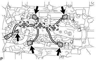
Disconnect the 4 knock sensor connectors.
Detach the 3 wire harness clamps.
Remove the bolt and engine wire.
| 27. REMOVE NO. 11 WATER BY-PASS HOSE |

| 28. REMOVE IGNITION COIL ASSEMBLY |
Remove the 8 bolts and 8 ignition coils.
| 29. REMOVE NOISE FILTER |
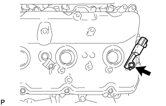
for Bank 1:
Remove the bolt and noise filter from the cylinder head cover LH.
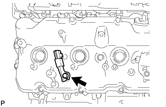
for Bank 2:
Remove the bolt and noise filter from the cylinder head cover RH.