Land Cruiser URJ200 URJ202 GRJ200 VDJ200 - 3UR-FE ENGINE MECHANICAL
ENGINE UNIT - INSTALLATION
| 1. INSTALL NOISE FILTER |
Install the 2 noise filters to the cylinder head cover with the 2 bolts.
- Torque:
- 7.0 N*m{ 71 kgf*cm, 62 in.*lbf}
| 2. INSTALL IGNITION COIL ASSEMBLY |
Install the 8 ignition coils with the 8 bolts.
- Torque:
- 10 N*m{ 102 kgf*cm, 7 ft.*lbf}
| 3. INSTALL FRONT NO. 1 ENGINE MOUNTING BRACKET LH |
Install the mounting bracket with the 4 bolts.
- Torque:
- 35 N*m{ 357 kgf*cm, 26 ft.*lbf}
| 4. INSTALL FRONT NO. 1 ENGINE MOUNTING BRACKET RH |
Install the mounting bracket with the 4 bolts.
- Torque:
- 35 N*m{ 357 kgf*cm, 26 ft.*lbf}
| 5. INSTALL CYLINDER BLOCK WATER DRAIN COCK SUB-ASSEMBLY |
Apply adhesive to 2 or 3 threads of the drain cocks.
- Adhesive:
- Toyota Genuine Adhesive 1344, Three Bond 1344 or equivalent

Install the water drain cocks as shown in the illustration.
- Torque:
- 30 N*m{ 306 kgf*cm, 22 ft.*lbf}
| *A | LH |
| *B | RH |
| *a | Front |
- NOTICE:
Install the water drain cock plugs to the water drain cocks.
- Torque:
- 13 N*m{ 133 kgf*cm, 10 ft.*lbf}
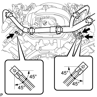
| 6. INSTALL KNOCK SENSOR |
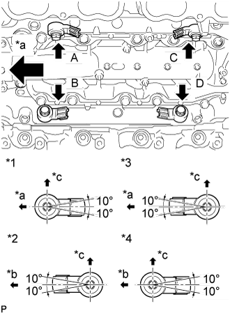
Install the 4 sensors with the 4 bolts so that the sensors are angled as shown in the illustration.
- Torque:
- 20 N*m{ 204 kgf*cm, 15 ft.*lbf}
| *1 | Bank 2 Sensor 1 |
| *2 | Bank 1 Sensor 1 |
| *3 | Bank 2 Sensor 2 |
| *4 | Bank 1 Sensor 2 |
| *a | Front |
| *b | Rear |
| *c | Top |
- NOTICE:
- The acceptable installation angle of the sensor is between 10° upward and downward from the horizontal position.
| 7. INSTALL SEPARATOR CASE |
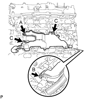
After inserting the pipe on the rear of the separator case into the oil return pipe and the pipe on the front into the ventilation pipe, temporarily install bolt A.
Temporarily install bolt B and tighten bolt A.
- Torque:
- 10 N*m{ 102 kgf*cm, 7 ft.*lbf}
Install the bolts labeled C.
- Torque:
- 10 N*m{ 102 kgf*cm, 7 ft.*lbf}
Tighten bolt B.
- Torque:
- 10 N*m{ 102 kgf*cm, 7 ft.*lbf}
- Standard Bolt:
Item Length Thread Diameter Bolt A 25 mm (0.984 in.) 6 mm (0.236 in.) Bolt B and C 16 mm (0.630 in.) 6 mm (0.236 in.)
| 8. INSTALL SENSOR WIRE |
Connect the 3 clamps and 4 knock sensor connectors.
| 9. INSTALL WATER BY-PASS PIPE SUB-ASSEMBLY |
Install the water by-pass pipe with the 2 bolts.
- Torque:
- 10 N*m{ 102 kgf*cm, 7 ft.*lbf}
| 10. INSTALL WATER INLET HOUSING |

Install a new gasket to the timing chain cover.
Install the water inlet with the 3 bolts.
- Torque:
- 21 N*m{ 214 kgf*cm, 15 ft.*lbf}
| *1 | Gasket |
| 11. INSTALL FRONT WATER BY-PASS JOINT |
Install 2 new gaskets and the water by-pass joint with the 4 nuts.
- Torque:
- 21 N*m{ 214 kgf*cm, 15 ft.*lbf}
Connect the No. 2 water by-pass hose to the water by-pass joint.
| 12. INSTALL NO. 1 WATER BY-PASS HOSE |
Install the No. 1 water by-pass hose by connecting the hose to the water inlet housing and front water by-pass joint.
| 13. INSTALL NO. 2 WATER BY-PASS PIPE SUB-ASSEMBLY |
Connect the 4 hoses.
Install the water by-pass pipe with the 3 bolts.
- Torque:
- 10 N*m{ 102 kgf*cm, 7 ft.*lbf}
| 14. INSTALL NO. 1 ENGINE COVER |
| 15. INSTALL NO. 2 ENGINE COVER |
| 16. INSTALL NO. 1 FUEL TUBE |
| 17. INSTALL NO. 2 FUEL TUBE |
Install the No. 2 fuel tube with the 2 bolts.
- Torque:
- 10 N*m{ 102 kgf*cm, 7 ft.*lbf}
| 18. INSTALL INTAKE MANIFOLD |
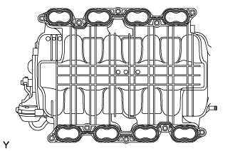
Place 2 new gaskets on the intake manifold.
Place the intake manifold on the cylinder head.
Install and uniformly tighten the 8 bolts and 2 nuts in several steps.
- Torque:
- 21 N*m{ 214 kgf*cm, 15 ft.*lbf}
Install the wire bracket to the intake manifold with the bolt.
- Torque:
- 8.0 N*m{ 82 kgf*cm, 71 in.*lbf}
Connect the No. 1 ventilation hose.
Connect the 2 water by-pass hoses.
Connect the ventilation hose to the ventilation pipe of the cylinder head cover LH and RH.
| 19. INSTALL FUEL INJECTOR ASSEMBLY |
Attach the 3 clamps to install the No. 6 wire harness to the delivery pipe RH.
Attach the 3 clamps to install the No. 7 wire harness to the delivery pipe LH.
Apply gasoline or spindle oil to a new O-ring and install it to the injector.
- NOTICE:
- Make sure that there is no damage or foreign material in the groove of the injector when installing the O-ring.
Connect the injector connector.
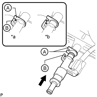
Install the injector to the delivery pipe as shown in the illustration.
| *a | CORRECT |
| *b | INCORRECT |
- NOTICE:
Check that each injector is installed to the delivery pipe facing the direction shown in the illustration.
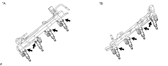
| *A | Fuel Delivery Pipe RH | *B | Fuel Delivery Pipe LH |
| 20. INSTALL FUEL DELIVERY PIPE SUB-ASSEMBLY RH |
Install the 2 delivery pipe spacers and 4 insulators to the cylinder head RH.
Install the delivery pipe (with injectors) to the cylinder head RH.
Install the 2 bolts.
- Torque:
- 21 N*m{ 214 kgf*cm, 15 ft.*lbf}
- NOTICE:
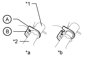
- Make sure that the part of the injector labeled B is between the parts of the delivery pipe labeled A.
| *1 | Delivery Pipe |
| *2 | Injector |
| *a | CORRECT |
| *b | INCORRECT |
Connect the No. 6 wire harness connector.
Connect the ventilation hose.
| 21. INSTALL FUEL DELIVERY PIPE SUB-ASSEMBLY LH |
Install the 2 delivery pipe spacers and 4 insulators to the cylinder head LH.
Install the delivery pipe (with injectors) to the cylinder head LH.
Install the 2 bolts.
- Torque:
- 21 N*m{ 214 kgf*cm, 15 ft.*lbf}
- NOTICE:
- Make sure that the part of the injector labeled B is between the parts of the delivery pipe labeled A.
| *1 | Delivery Pipe |
| *2 | Injector |
| *a | CORRECT |
| *b | INCORRECT |
Connect the No. 7 wire harness connector.
| 22. CONNECT NO. 1 FUEL TUBE |
LH Side:
Connect the No. 1 fuel tube to the delivery pipe LH ().
Connect the No. 1 fuel tube to the delivery pipe RH (for metallic type) ().
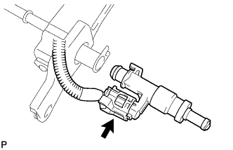
| 23. CONNECT NO. 2 FUEL TUBE |
Connect the No. 2 fuel tube to the fuel pressure regulator ().
| 24. INSTALL NO. 1 FUEL HOSE |
Install the fuel hose ().
| 25. INSTALL NO. 3 ENGINE COVER |
| 26. INSTALL NO. 1 ENGINE COVER SUB-ASSEMBLY |
| 27. INSTALL ENGINE WIRE |
Install the engine wire.
Engine Rear Side:
Install the 3 bolts as shown in the illustration.
- Torque:
- 8.5 N*m{ 87 kgf*cm, 75 in.*lbf}
Connect the 5 clamps.
Connect the sensor wire connector.
Engine RH Side:
Connect the 9 clamps.
Connect the oil pressure sender gauge connector.
Connect the throttle sensor connector.
Connect the noise filter connector.
Connect the fuel injector connector.
Connect the 2 VVT sensor connectors.
- HINT:
- The wire harnesses on the exhaust side are wrapped with white tape.
Connect the 4 ignition coil connectors.
Connect the 2 camshaft timing control valve connectors.
- HINT:
- The wire harnesses on the exhaust side are wrapped with white tape.
Engine LH Side:
Connect the 7 clamps and install the engine wire with the bolt.
- Torque:
- 20 N*m{ 204 kgf*cm, 15 ft.*lbf}
Connect the noise filter connector.
Connect the fuel injector connector.
Connect the engine coolant temperature sensor connector.
Connect the purge VSV connector.
Connect the vacuum switching valve connector (for ACIS).
Connect the camshaft position sensor connector.
Connect the 2 VVT sensor connectors.
- HINT:
- The wire harnesses on the exhaust side are wrapped with white tape.
Connect the 4 ignition coil connectors.
Connect the 2 camshaft timing control valve connectors.
- HINT:
- The wire harnesses on the exhaust side are wrapped with white tape.