Land Cruiser URJ200 URJ202 GRJ200 VDJ200 - 1GR-FE ENGINE CONTROL
CHECK HARNESS AND CONNECTOR (KNOCK SENSOR - ECM)
DTC P0327 Knock Sensor 1 Circuit Low Input (Bank 1 or Single Sensor)
DTC P0328 Knock Sensor 1 Circuit High Input (Bank 1 or Single Sensor)
DTC P0332 Knock Sensor 2 Circuit Low Input (Bank 2)
DTC P0333 Knock Sensor 2 Circuit High Input (Bank 2)
DESCRIPTION
Flat-type knock sensors (non-resonant type) have structures that can detect vibrations between approximately 6 kHz and 15 kHz.
2 knock sensors are fitted onto the engine block to detect engine knocking.
Each knock sensor contains a piezoelectric element which generates a voltage when it becomes deformed.
The voltage is generated when the engine block vibrates due to knocking. Any occurrence of engine knocking can be suppressed by delaying the ignition timing.
| DTC No. | DTC Detection Condition | Trouble Area |
| P0327 P0332 | Output voltage of the knock sensor is below 0.5 V (1 trip detection logic). | Short in knock sensor circuit Knock sensor ECM |
| P0328 P0333 | Output voltage of the knock sensor is higher than 4.5 V (1 trip detection logic). | Open in knock sensor circuit Knock sensor ECM |
- HINT:
- When DTC P0327, P0328, P0332 or P0333 is stored, the ECM enters fail-safe mode. During fail-safe mode, the ignition timing is delayed to its maximum retardation. The ECM continues operating in fail-safe mode until the ignition switch is turned off.
Reference: Inspection using an oscilloscope
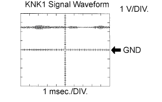
The correct waveform is as shown.
| Item | Content |
| Terminal | KNK1 - EKNK KNK2 - EKN2 |
| Equipment Setting | 1 V/DIV. 0.01 to 1 msec./DIV. |
| Condition | Engine speed at 4000 rpm with warm engine |
MONITOR DESCRIPTION
If the output voltage transmitted by the knock sensor remains low or high for more than 1 second, the ECM interprets this as a malfunction in the sensor circuit and stores a DTC.
The monitor for DTCs P0327, P0328, P0332 and P0333 begins to run 5 seconds after the engine is started.
If the malfunction is not repaired successfully, DTC P0327, P0328, P0332 or P0333 is stored 5 seconds after the engine is next started.
WIRING DIAGRAM

INSPECTION PROCEDURE
- HINT:
*: The No. 1 cylinder is the cylinder which is farthest from the transmission.
| 1.CHECK KNOCK SENSOR |
Disconnect the ECM connector.
Measure the resistance according to the value(s) in the table below.
- Standard Resistance:
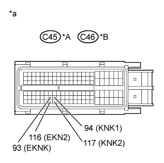
for LHD Tester Connection Condition Specified Condition C45-94 (KNK1) - C45-93 (EKNK) 20°C (68°F) 120 to 280 kΩ C45-117 (KNK2) - C45-116 (EKN2) 20°C (68°F) 120 to 280 kΩ for RHD Tester Connection Condition Specified Condition C46-94 (KNK1) - C46-93 (EKNK) 20°C (68°F) 120 to 280 kΩ C46-117 (KNK2) - C46-116 (EKN2) 20°C (68°F) 120 to 280 kΩ
| *A | for LHD |
| *B | for RHD |
| *a | Rear view of wire harness connector (to ECM) |
|
| ||||
| OK | |
| 2.CHECK TERMINAL VOLTAGE (ECM) |
Disconnect the CU1 connector.
Turn the ignition switch to ON.
Measure the voltage according to the value(s) in the table below.
- Standard Voltage:
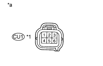
Tester Connection Switch Condition Specified Condition CU1 female connector 2 - 5 Ignition switch ON 4.5 to 5.5 V CU1 female connector 4 - 6 Ignition switch ON 4.5 to 5.5 V
| *1 | Female |
| *a | Front view of wire harness connector (to ECM Wire) |
|
| ||||
| OK | ||
| ||
| 3.CHECK HARNESS AND CONNECTOR (KNOCK SENSOR - ECM) |
Disconnect the knock sensor connectors.
Disconnect the ECM connector.
Measure the resistance according to the value(s) in the table below.
- Standard Resistance:
for LHD Tester Connection Condition Specified Condition U2-2 - C45-94 (KNK1) Always Below 1 Ω U2-1 - C45-93 (EKNK) Always Below 1 Ω U1-2 - C45-117 (KNK2) Always Below 1 Ω U1-1 - C45-116 (EKN2) Always Below 1 Ω U2-2 or C45-94 (KNK1) - Body ground Always 10 kΩ or higher U2-1 or C45-93 (EKNK) - Body ground Always 10 kΩ or higher U1-2 or C45-117 (KNK2) - Body ground Always 10 kΩ or higher U1-1 or C45-116 (EKN2) - Body ground Always 10 kΩ or higher for RHD Tester Connection Condition Specified Condition U2-2 - C46-94 (KNK1) Always Below 1 Ω U2-1 - C46-93 (EKNK) Always Below 1 Ω U1-2 - C46-117 (KNK2) Always Below 1 Ω U1-1 - C46-116 (EKN2) Always Below 1 Ω U2-2 or C46-94 (KNK1) - Body ground Always 10 kΩ or higher U2-1 or C46-93 (EKNK) - Body ground Always 10 kΩ or higher U1-2 or C46-117 (KNK2) - Body ground Always 10 kΩ or higher U1-1 or C46-116 (EKN2) - Body ground Always 10 kΩ or higher
|
| ||||
| OK | ||
| ||