Land Cruiser URJ200 URJ202 GRJ200 VDJ200 - 1UR-FE ENGINE CONTROL
INSPECT AIR FUEL RATIO SENSOR (HEATER RESISTANCE)
CHECK TERMINAL VOLTAGE (+B OF AIR FUEL RATIO SENSOR)
CHECK HARNESS AND CONNECTOR (AIR FUEL RATIO SENSOR - ECM)
CHECK WHETHER DTC OUTPUT RECURS
INSPECT NO. 1 INTEGRATION RELAY (A/F)
CHECK HARNESS AND CONNECTOR (NO. 1 INTEGRATION RELAY - AIR FUEL RATIO SENSOR AND BODY GROUND)
DTC P0031 Oxygen (A/F) Sensor Heater Control Circuit Low (Bank 1 Sensor 1)
DTC P0032 Oxygen (A/F) Sensor Heater Control Circuit High (Bank 1 Sensor 1)
DTC P0051 Oxygen (A/F) Sensor Heater Control Circuit Low (Bank 2 Sensor 1)
DTC P0052 Oxygen (A/F) Sensor Heater Control Circuit High (Bank 2 Sensor 1)
DTC P101D A/F Sensor Heater Circuit Performance Bank 1 Sensor 1 Stuck ON
DTC P103D A/F Sensor Heater Circuit Performance Bank 2 Sensor 1 Stuck ON
DESCRIPTION
Refer to DTC P2195 ().
- HINT:

| DTC No. | DTC Detection Condition | Trouble Area |
| P0031 P0051 | Air fuel ratio sensor heater current is below 0.8 A, even when the air fuel ratio sensor heater duty cycle is 50% or more (1 trip detection logic). | Open in air fuel ratio sensor heater circuit Air fuel ratio sensor heater (for Sensor 1) No. 1 integration relay ECM |
| P0032 P0052 | Air fuel ratio sensor heater current reaches the high limit (Hybrid IC high current limiter port "Fail") (1 trip detection logic). | Short in air fuel ratio sensor heater circuit Air fuel ratio sensor heater (for Sensor 1) No. 1 integration relay ECM |
| P101D P103D | The heater current is higher than the specified value (1 trip detection logic). | ECM |
MONITOR DESCRIPTION
The ECM uses information from the air fuel ratio sensor to regulate the air-fuel ratio and keep it close to the stoichiometric level. This maximizes the ability of the Three-way Catalytic Converter (TWC) to purify the exhaust gases.
The air fuel ratio sensor detects oxygen levels in the exhaust gas and transmits the information to the ECM. The inner surface of the sensor element is exposed to the outside air. The outer surface of the sensor element is exposed to the exhaust gas. The sensor element is made of platinum coated zirconia and includes an integrated heating element.
The zirconia element generates a small voltage when there is a large difference in the oxygen concentrations between the exhaust gas and outside air. The platinum coating amplifies this voltage generation.
The air fuel ratio sensor is more efficient when heated. When the exhaust gas temperature is low, the sensor cannot generate useful voltage signals without supplementary heating. The ECM regulates the supplementary heating using a duty cycle approach to adjust the average current in the sensor heater element. If the heater current is outside the normal range, the signal transmitted by the air fuel ratio sensor becomes inaccurate. As a result, the ECM is unable to regulate the air-fuel ratio properly.
When the current in the air fuel ratio sensor heater is outside the normal operating range, the ECM interprets this as a malfunction in the sensor heater and stores a DTC.
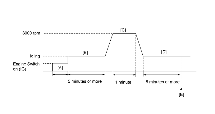
CONFIRMATION DRIVING PATTERN
- HINT:
| GTS Display | Description |
| NORMAL | DTC judgment completed System normal |
| ABNORMAL | DTC judgment completed System abnormal |
| INCOMPLETE | DTC judgment not completed Perform driving pattern after confirming DTC enabling conditions |
| N/A | Unable to perform DTC judgment Number of DTCs which do not fulfill DTC preconditions has reached ECU memory limit |
- HINT:
WIRING DIAGRAM
Refer to DTC P2195 ().
INSPECTION PROCEDURE
- NOTICE:
- Inspect the fuses of circuits related to this system before performing the following inspection procedure.
- HINT:
*: The No. 1 cylinder is the cylinder which is farthest from the transmission.
| 1.INSPECT AIR FUEL RATIO SENSOR (HEATER RESISTANCE) |
Inspect the air fuel ratio sensor ().
|
| ||||
| OK | |
| 2.CHECK TERMINAL VOLTAGE (+B OF AIR FUEL RATIO SENSOR) |
Disconnect the air fuel ratio sensor connector.
Turn the engine switch on (IG).
Measure the voltage according to the value(s) in the table below.
- Standard Voltage:
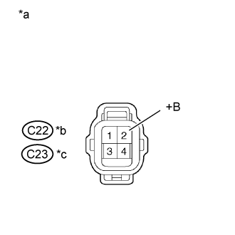
Tester Connection Switch Condition Specified Condition C22-2 (+B) - Body ground Engine switch on (IG) 11 to 14 V C23-2 (+B) - Body ground Engine switch on (IG) 11 to 14 V
| *a | Front view of wire harness connector (to Air Fuel Ratio Sensor) |
| *b | Bank 1 |
| *c | Bank 2 |
|
| ||||
| OK | |
| 3.CHECK HARNESS AND CONNECTOR (AIR FUEL RATIO SENSOR - ECM) |
Disconnect the air fuel ratio sensor connector.
Disconnect the ECM connector.
Measure the resistance according to the value(s) in the table below.
- Standard Resistance:
for RHD Tester Connection Condition Specified Condition C22-1 (HA1A) - C46-22 (HA1A) Always Below 1 Ω C23-1 (HA2A) - C46-20 (HA2A) Always Below 1 Ω C22-1 (HA1A) or C46-22 (HA1A) - Body ground Always 10 kΩ or higher C23-1 (HA2A) or C46-20 (HA2A) - Body ground Always 10 kΩ or higher for LHD Tester Connection Condition Specified Condition C22-1 (HA1A) - C45-22 (HA1A) Always Below 1 Ω C23-1 (HA2A) - C45-20 (HA2A) Always Below 1 Ω C22-1 (HA1A) or C45-22 (HA1A) - Body ground Always 10 kΩ or higher C23-1 (HA2A) or C45-20 (HA2A) - Body ground Always 10 kΩ or higher
|
| ||||
| OK | |
| 4.CHECK WHETHER DTC OUTPUT RECURS |
Connect the GTS to the DLC3.
Turn the engine switch on (IG).
Turn the GTS on.
Clear DTCs ().
Start the engine.
Drive the vehicle in accordance with the driving pattern described in Confirmation Driving Pattern.
Read the output pending DTCs using the GTS.
| Result | Proceed to |
| No pending DTC is output | A |
| Pending DTC P0031, P0032, P0051, P0052, P101D or P103D is output | B |
|
| ||||
| A | ||
| ||
| 5.INSPECT NO. 1 INTEGRATION RELAY (A/F) |
Inspect the No. 1 integration relay (A/F) ().
|
| ||||
| OK | |
| 6.CHECK HARNESS AND CONNECTOR (NO. 1 INTEGRATION RELAY - AIR FUEL RATIO SENSOR AND BODY GROUND) |
Disconnect the air fuel ratio sensor connector.
Remove the No. 1 integration relay from the engine room relay block.
Measure the resistance according to the value(s) in the table below.
- Standard Resistance:
Tester Connection Condition Specified Condition C22-2 (+B) - 1A-4 Always Below 1 Ω C23-2 (+B) - 1A-4 Always Below 1 Ω 1A-3 - Body ground Always Below 1 Ω C22-2 (+B) or 1A-4 - Body ground Always 10 kΩ or higher C23-2 (+B) or 1A-4 - Body ground Always 10 kΩ or higher
|
| ||||
| OK | ||
| ||