Land Cruiser URJ200 URJ202 GRJ200 VDJ200 - AXLE AND DIFFERENTIAL
FRONT AXLE HUB BOLT - REPLACEMENT
- HINT:
| 1. REMOVE STABILIZER CONTROL VALVE PROTECTOR (w/ KDSS) |
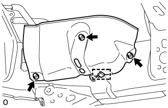
Detach the clamp, and disconnect the connector from the protector.
Remove the 3 bolts and protector.
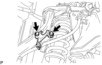
| 2. OPEN STABILIZER CONTROL WITH ACCUMULATOR HOUSING SHUTTER VALVE (w/ KDSS) |
Using a 5 mm hexagon socket wrench, loosen the lower and upper chamber shutter valves of the stabilizer control with accumulator housing 2.0 to 3.5 turns.

- NOTICE:
| 3. REMOVE FRONT WHEEL |
| 4. DISCONNECT FRONT DISC BRAKE CALIPER ASSEMBLY LH |
Remove the bolt and nut, and disconnect the brake tube bracket from the steering knuckle.

Remove the 2 bolts and disconnect the disc brake caliper from the steering knuckle.
- NOTICE:
| 5. REMOVE FRONT DISC |

Put matchmarks on the front disc and axle hub if planning to reuse the disc.
Remove the front disc.
| 6. REMOVE FRONT AXLE HUB BOLT LH |
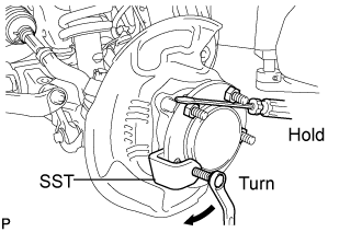
Using SST and a screwdriver or equivalent to hold the axle hub, remove the front axle hub bolt.
- SST
- 09650-17011
- NOTICE:
- Do not damage the threads of the hub bolt.
| 7. INSTALL FRONT AXLE HUB BOLT LH |
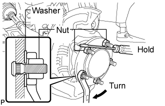
Temporarily install a washer and hub nut to a new hub bolt as shown in the illustration.
- NOTICE:
- Install a hub nut to prevent damage to the hub bolt.
Using a screwdriver or equivalent to hold the hub, turn the hub nut until the bottom surface of the hub bolt head touches the axle hub.
Remove the washer and hub nut.
- NOTICE:
- Do not damage the threads of the hub bolt.
| 8. INSPECT FRONT AXLE HUB BEARING LOOSENESS |
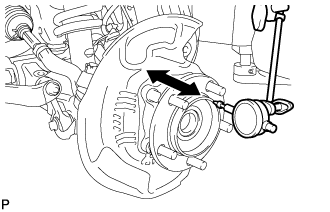
Using a dial indicator, measure the looseness near the center of the axle hub.
- Maximum looseness:
- 0.05 mm (0.00197 in.)
- NOTICE:
- Ensure that the dial indicator is set at a right angle to the measurement surface.
If the looseness exceeds the maximum, replace the axle hub.
| 9. INSPECT FRONT AXLE HUB RUNOUT |
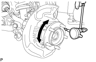
Using a dial indicator, measure the runout on the surface of the axle hub outside the hub bolt.
- Maximum runout:
- 0.08 mm (0.00315 in.)
- NOTICE:
- Ensure that the dial indicator is set at a right angle to the measurement surface.
If the runout exceeds the maximum, replace the axle hub.
| 10. INSTALL FRONT DISC |
Align the matchmarks, and then install the front disc.
- HINT:
- When replacing the front disc with a new one, select the installation position where the front disc has the minimum runout.
| 11. CONNECT FRONT DISC BRAKE CALIPER ASSEMBLY LH |
Connect the front disc brake caliper and install 2 new bolts.
- Torque:
- 99 N*m{ 1010 kgf*cm, 73 ft.*lbf}
- NOTICE:

Connect the brake tube bracket to the steering knuckle with the bolt and nut.
- Torque:
- for bolt:
- 31 N*m{ 316 kgf*cm, 23 ft.*lbf}
- for nut:
- 13 N*m{ 132 kgf*cm, 10 ft.*lbf}
| 12. INSTALL FRONT WHEEL |
- Torque:
- for Aluminum Wheel:
- 131 N*m{ 1336 kgf*cm, 97 ft.*lbf}
- for Steel Wheel:
- 209 N*m{ 2131 kgf*cm, 154 ft.*lbf}
| 13. MEASURE VEHICLE HEIGHT (w/ KDSS) |
- NOTICE:
- HINT:
Set the tire pressure to the specified value(s) ().
Bounce the vehicle to stabilize the suspension.

Measure the distance from the ground to the top of the bumper and calculate the difference in the vehicle height between left and right. Perform this procedure for both the front and rear wheels.
- Height difference of left and right sides:
- 15 mm (0.591 in.) or less
- HINT:
- If not as specified, perform the vehicle tilt calibration.
| 14. CLOSE STABILIZER CONTROL WITH ACCUMULATOR HOUSING SHUTTER VALVE (w/ KDSS) |
- NOTICE:
- HINT:
Using a 5 mm hexagon socket wrench, tighten the lower and upper chamber shutter valves of the stabilizer control with accumulator housing.
- Torque:
- 14 N*m{ 143 kgf*cm, 10 ft.*lbf}
| 15. INSTALL STABILIZER CONTROL VALVE PROTECTOR (w/ KDSS) |
Install the valve protector with the 3 bolts.
- Torque:
- 18 N*m{ 184 kgf*cm, 13 ft.*lbf}
Attach the clamp, and connect the connector to the valve protector.