Land Cruiser URJ200 URJ202 GRJ200 VDJ200 - PARK ASSIST / MONITORING
CHECK HARNESS AND CONNECTOR (PARKING ASSIST ECU - BATTERY AND BODY GROUND)
TOYOTA PARKING ASSIST-SENSOR SYSTEM - ECU Power Source Circuit
DESCRIPTION
This circuit is the power source circuit to operate the parking assist ECU. The parking assist ECU controls the TOYOTA parking assist-sensor system, parking assist monitor system (w/ Side Monitor System), side monitor system and wide view front monitor system. When a malfunction occurs in this circuit, each system will be abnormal.
WIRING DIAGRAM

INSPECTION PROCEDURE
- NOTICE:
- Inspect the fuses for circuits related to this system before performing the following inspection procedure.
| 1.CHECK HARNESS AND CONNECTOR (PARKING ASSIST ECU - BATTERY AND BODY GROUND) |
Disconnect the parking assist ECU connector.
Measure the resistance according to the value(s) in the table below.
- Standard Resistance:
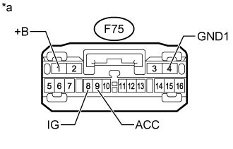
Tester Connection Condition Specified Condition F75-4 (GND1) - Body ground Always Below 1 Ω
Measure the voltage according to the value(s) in the table below.
- Standard Voltage:
Tester Connection Condition Specified Condition F75-1 (+B) - F75-4 (GND1) Always 11 to 14 V F75-8 (IG) - F75-4 (GND1) Engine switch on (IG) 11 to 14 V F75-9 (ACC) - F75-4 (GND1) Engine switch on (ACC) 11 to 14 V
| *a | Front view of wire harness connector (to Parking Assist ECU) |
|
| ||||
| OK | ||
| ||