Land Cruiser URJ200 URJ202 GRJ200 VDJ200 - AUDIO / VIDEO
STEREO COMPONENT AMPLIFIER - REMOVAL
| 1. PRECAUTION |
- NOTICE:
- After turning the ignition switch off, waiting time may be required before disconnecting the cable from the battery terminal. Therefore, make sure to read the disconnecting the cable from the battery terminal notice before proceeding with work ().
| 2. DISCONNECT CABLE FROM NEGATIVE BATTERY TERMINAL |
- CAUTION:
- Wait at least 90 seconds after disconnecting the cable from the negative (-) battery terminal to disable the SRS system.
- NOTICE:
- When disconnecting the cable, some systems need to be initialized after the cable is reconnected ().
| 3. REMOVE FRONT SEAT ASSEMBLY LH |
for Manual Seat:
Remove the front seat assembly LH ().
for Power Seat:
Remove the front seat assembly LH ().
| 4. REMOVE FRONT SEAT ASSEMBLY RH |
for Manual Seat:
Remove the front seat assembly RH ().
for Power Seat:
Remove the front seat assembly RH ().
- HINT:
- Use the same procedures described for the LH side.
| 5. REMOVE REAR NO. 3 SEAT CUSHION HINGE COVER |
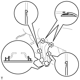
Using a screwdriver, detach the 6 claws and remove the cover.
- HINT:
- Tape the screwdriver tip before use.
| 6. REMOVE REAR NO. 5 SEAT CUSHION HINGE COVER |

Using a screwdriver, detach the 7 claws and remove the cover.
- HINT:
- Tape the screwdriver tip before use.
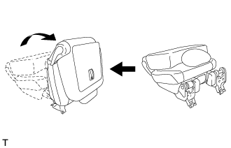
| 7. REMOVE REAR NO. 2 SEAT CUSHION HINGE COVER |

Operate the reclining adjuster release handle to move the seat into the position shown in the illustration.

Using a screwdriver, detach the 2 claws and 2 clips, and remove the cover.
- HINT:
- Tape the screwdriver tip before use.
| 8. REMOVE REAR NO. 4 SEAT CUSHION HINGE COVER |

Using a screwdriver, detach the 2 claws and 2 clips, and remove the cover.
- HINT:
- Tape the screwdriver tip before use.
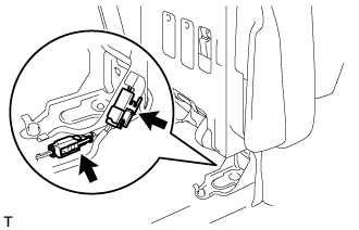
| 9. REMOVE REAR NO. 1 SEAT ASSEMBLY LH |
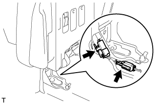
w/ Rear Seat Side Airbag:
Disconnect the connector.
w/ Seat Heater System:
Disconnect the connector.
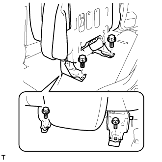
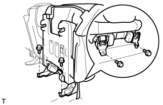
Remove the 4 bolts and seat assembly.
- NOTICE:
- Be careful not to damage the vehicle body.
| 10. REMOVE REAR NO. 2 SEAT CUSHION HINGE COVER |
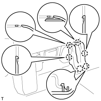
Using a screwdriver, detach the 6 claws and remove the cover.
- HINT:
- Tape the screwdriver tip before use.
| 11. REMOVE REAR NO. 4 SEAT CUSHION HINGE COVER |

Using a screwdriver, detach the 7 claws and remove the cover.
- HINT:
- Tape the screwdriver tip before use.
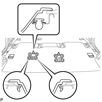
| 12. REMOVE REAR NO. 1 SEAT CUSHION HINGE COVER |
Operate the reclining adjuster release handle to move the seat into the position shown in the illustration.

Using a screwdriver, detach the 2 claws and 2 clips, and remove the cover.
- HINT:
- Tape the screwdriver tip before use.
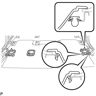
| 13. REMOVE REAR NO. 3 SEAT CUSHION HINGE COVER |

Using a screwdriver, detach the 2 claws and 2 clips, and remove the cover.
- HINT:
- Tape the screwdriver tip before use.
| 14. REMOVE REAR NO. 1 SEAT ASSEMBLY RH |
w/ Rear Seat Side Airbag:
Disconnect the connector.
w/ Seat Heater System:
Disconnect the connector.
Remove the 4 bolts and seat assembly.
- NOTICE:
- Be careful not to damage the vehicle body.
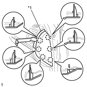
| 15. REMOVE INSTRUMENT SIDE PANEL LH |
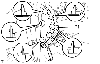
Place protective tape as shown in the illustration.
| *1 | Protective Tape |
Using a moulding remover, detach the 6 claws and remove the instrument side panel.
| 16. REMOVE INSTRUMENT SIDE PANEL RH (w/o Airbag Cut Off Switch) |
Place protective tape as shown in the illustration.
| *1 | Protective Tape |
Using a moulding remover, detach the 6 claws and remove the instrument side panel.
| 17. REMOVE INSTRUMENT SIDE PANEL RH (w/ Airbag Cut Off Switch) |
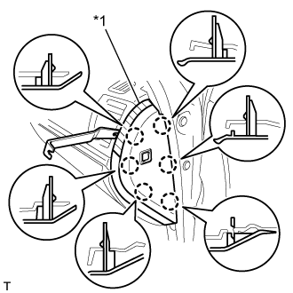
Place protective tape as shown in the illustration.
| *1 | Protective Tape |
Using a moulding remover, detach the 6 claws.
Disconnect the connector and remove the instrument side panel.
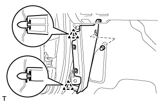
| 18. REMOVE FRONT DOOR SCUFF PLATE LH |

Detach the 7 claws and 4 clips, and remove the scuff plate.
| 19. REMOVE FRONT DOOR SCUFF PLATE RH |
- HINT:
- Use the same procedures described for the LH side.
| 20. REMOVE NO. 1 INSTRUMENT PANEL UNDER COVER SUB-ASSEMBLY (w/ Floor Under Cover) |

Remove the 2 screws.
Detach the 3 claws.
Disconnect the connectors and remove the No. 1 instrument panel under cover.
| 21. REMOVE COWL SIDE TRIM BOARD LH |
Remove the cap nut.
Detach the 2 clips and remove the cowl side trim board.
| 22. REMOVE NO. 2 INSTRUMENT PANEL UNDER COVER SUB-ASSEMBLY (w/ Floor Under Cover) |
Detach the 4 claws and remove the No. 2 instrument panel under cover.
| 23. REMOVE COWL SIDE TRIM BOARD RH |

Remove the cap nut.
Detach the 2 clips and remove the cowl side trim board.
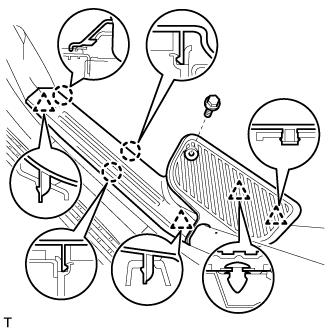
| 24. REMOVE REAR STEP COVER |

- HINT:
- Use the same procedure to remove the step cover on the other side.
Detach the 2 claws and remove the step cover.
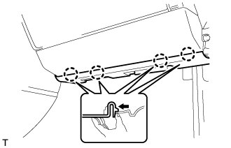
| 25. REMOVE REAR DOOR SCUFF PLATE LH |
Remove the screw.
Detach the 3 claws and 4 clips, and remove the scuff plate.
| 26. REMOVE REAR DOOR SCUFF PLATE RH |
- HINT:
- Use the same procedures described for the LH side.
| 27. REMOVE NO. 2 AIR DUCT PLUG |

Detach the 4 claws and remove the 2 plugs.
- HINT:
- Use the same procedures for both sides.
| 28. REMOVE AIR HEATER GUIDE |
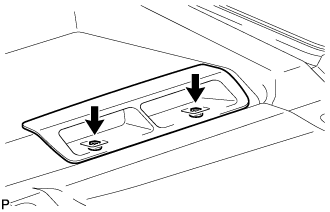
Remove the 2 screws and guide.
- HINT:
- Use the same procedures for both sides.
| 29. REMOVE AIR DUCT PLUG |
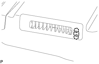
Detach the 2 claws and remove the plug.
- HINT:
- Use the same procedures for both sides.
| 30. REMOVE REAR AIR DUCT GUIDE |
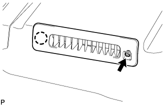
Remove the screw.
Detach the claw and remove the guide.
- HINT:
- Use the same procedures for both sides.
| 31. REMOVE REAR NO. 1 SEAT PROTECTOR |
Detach the clip and 4 claws, and remove the protector.
- HINT:
- Use the same procedures to remove the protector on the other side.
| 32. REMOVE REAR NO. 2 SEAT PROTECTOR |
Detach the clip and 4 claws, and remove the protector.
- HINT:
- Use the same procedures to remove the protector on the other side.
| 33. REMOVE COOLING BOX ASSEMBLY (w/ Cool Box) |
Remove the cooling box assembly ().
| 34. REMOVE REAR CONSOLE BOX SUB-ASSEMBLY (w/o Cool Box) |
Remove the rear console box sub-assembly ().
| 35. REMOVE FRONT FLOOR CARPET ASSEMBLY |
Detach the 2 clips and 8 claws.

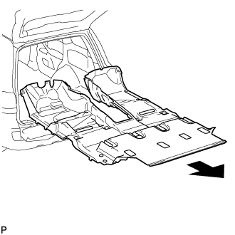
Remove the carpet from the floor, open the back door and tail gate, and remove the carpet from the rear of the vehicle.
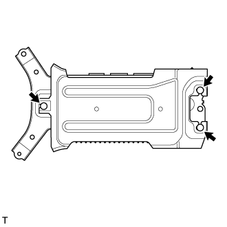
| 36. REMOVE STEREO COMPONENT AMPLIFIER ASSEMBLY WITH BRACKET |

Disconnect the 3 connectors.
Remove the 3 bolts and remove the amplifier with bracket.
| 37. REMOVE AMPLIFIER COVER |
Detach the 3 clips and remove the cover.
| 38. REMOVE NO. 1 AMPLIFIER BRACKET |
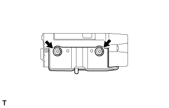
Remove the 2 screws and bracket.
| 39. REMOVE NO. 2 AMPLIFIER BRACKET |

Remove the 2 screws and bracket.