Land Cruiser URJ200 URJ202 GRJ200 VDJ200 - PARK ASSIST / MONITORING
SIDE MONITOR SYSTEM - TERMINALS OF ECU
| PARKING ASSIST ECU |
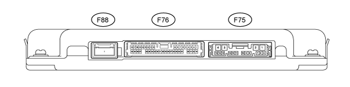
Disconnect the F75 and F76 parking assist ECU connectors.
Measure the voltage and resistance according to the value(s) in the table below.
| Terminal No. (Symbol) | Wiring Color | Terminal Description | Condition | Specified Condition |
| F75-1 (+B) - F75-4 (GND1) | L - W-B | Power source signal | Always | 11 to 14 V |
| F75-4 (GND1) - Body ground | W-B - Body ground | Ground | Always | Below 1 Ω |
| F75-8 (IG) - F75-4 (GND1) | G - W-B | IG Power source signal | Engine switch on (IG) | 11 to 14 V |
| Engine switch off | Below 1 V | |||
| F75-9 (ACC) - F75-4 (GND1) | GR - W-B | ACC Power source signal | Engine switch off (ACC) | 11 to 14 V |
| Engine switch off | Below 1 V | |||
| F76-7 (BLSW) - F75-4 (GND1) | G - W-B | Front and side monitor main switch power source signal | Engine switch on (IG), front and side monitor main switch assembly on | 11 to 14 V |
Reconnect the F75 and F76 parking assist ECU connectors.
Measure the voltage according to the value(s) in the table below.
| Terminal No. (Symbol) | Wiring Color | Terminal Description | Condition | Specified Condition |
| F76-39 (CANL) - F75-4 (GND1) | L - W-B | CAN communication signal | CAN communication circuit | Pulse generation |
| FF76-40 (CANH) - F75-4 (GND1) | V - W-B | CAN communication signal | CAN communication circuit | Pulse generation |
| F75-10 (TX-) | L | AVC-LAN communication signal | - | - |
| F75-11 (TX+) | W | AVC-LAN communication signal | - | - |
| F76-34 (SCV-) - F76-33 (SGND) | W - Shielded | Side television camera ground | Always | Below 1 V |
| F76-10 (SCV+) - F76-33 (SGND) | R - Shielded | Side television camera display signal input | Engine switch on (IG), front and side monitor main switch assembly on | Pulse generation (See waveform) |
| F76-33 (SGND) - F75-4 (GND1) | Shielded - W-B | Side television camera ground (shield) | Always | Below 1 V |
| F76-32 (SCB+) - F76-33 (SGND) | B - Shielded | Power source to side television camera | Engine switch on (IG), shift lever in R | 5.5 to 7.05 V |
| F76-31 (DCV-) - F76-29 (DGND) | W - Shielded | Side television camera ground | Always | Below 1 V |
| F76-30 (DCV+) - F76-29 (DGND) | R - Shielded | Side television camera display signal input | Engine switch on (IG), front and side monitor main switch assembly on | Pulse generation (See waveform) |
| F76-29 (DGND) - F75-4 (GND1) | Shielded - W-B | Side television camera ground (shield) | Always | Below 1 V |
| F76-28 (DCB+) - F76-29 (DGND) | B - Shielded | Power source to side television camera | Engine switch on (IG), front and side monitor main switch assembly on | 5.5 to 7.05 V |
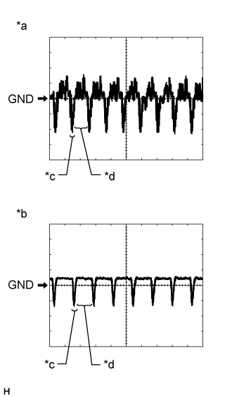
Using an oscilloscope, check waveform.
| *a | Waveform A (under normal conditions) |
| *b | Waveform B (camera lens is covered, blacking out the screen) |
| *c | Synchronized Signal |
| *d | Video Waveform |
- HINT:
- The video waveform changes according to the image sent by the side television camera assembly.
Waveform
| Item | Content |
| Terminal No. (Symbol) | F76-10 (SCV+) - F76-33 (SGND) F76-30 (DCV+) - F76-29 (DGND) |
| Tool Setting | 200 mV/DIV., 50 μsec./DIV. |
| Condition | Waveform A: Engine switch on (IG), front and side monitor main switch assembly on and camera lens is not covered, displaying an image Waveform B: Engine switch on (IG), front and side monitor main switch assembly on and camera lens is not covered, displaying an image. |
| SIDE TELEVISION CAMERA ASSEMBLY |

Disconnect the side television camera assembly connector.
Measure the voltage according to the value(s) in the table below.
| Terminal No. (Symbol) | Terminal Description | Condition | Specified Condition |
| 4 - Body ground | Ground | Always | Below 1 V |
| 1 - 4 | Power source | Engine switch on (IG) Front and side monitor main switch on | 5.5 to 7.05 V |
Reconnect the side television camera assembly connector.
- HINT:
- A waterproof connector is used for the front television camera assembly. Therefore, inspect the waveform at the parking assist ECU with the connector connected.
Measure the voltage according to the value(s) in the table below.
| Terminal No. (Symbol) | Terminal Description | Condition | Specified Condition |
| 3 - 4 | Display signal | Engine switch on (IG), front and side monitor main switch assembly on | Pulse generation (See waveform) |
| 4 - 6 | Rear television camera ground | Always | Below 1 V |
Using an oscilloscope, check waveform.
| *a | Waveform A (under normal conditions) |
| *b | Waveform B (camera lens is covered, blacking out the screen) |
| *c | Synchronized Signal |
| *d | Video Waveform |
- HINT:
- The video waveform changes according to the image sent by the side television camera assembly.
Waveform 1
| Item | Content |
| Terminal No. (Symbol) | 3 - 4 |
| Tool Setting | 200 mV/DIV., 50 μsec./DIV. |
| Condition | Waveform A: Engine switch on (IG), front and side monitor main switch assembly on and camera lens is not covered, displaying an image. Waveform B: Engine switch on (IG), front and side monitor main switch assembly on and camera lens is covered, blacking out the screen. |
| MULTI-MEDIA MODULE RECEIVER ASSEMBLY () |
| MULTI-DISPLAY ASSEMBLY () |