Land Cruiser URJ200 URJ202 GRJ200 VDJ200 - NAVIGATION / MULTI INFO DISPLAY
NAVIGATION SYSTEM - TERMINALS OF ECU
| MULTI-MEDIA MODULE RECEIVER ASSEMBLY |

| Terminal No. (Symbol) | Wiring Color | Terminal Description | Condition | Specified Condition |
| F77-1 (CANH) | B | CAN communication signal | - | - |
| F77-2 (CANL) | W | CAN communication signal | - | - |
| F77-7 (TX1+) | W | AVC-LAN communication signal | - | - |
| F77-8 (TX1-) | L | AVC-LAN communication signal | - | - |
| F77-10 (VMTF) - F77-12 (GND1) | V - W-B | Visual mute signal | When image on display switches | 3.5 V or higher → Below 1 V → 3.5 V or higher |
| F77-12 (GND1) - Body ground | W-B - Body ground | Ground | Always | Below 1 Ω |
| F77-13 (ILL-) - F77-12 (GND1) | W - W-B | Illumination signal | Engine switch on (IG), light control switch off → tail or head position | Below 1 V → Pulse generation |
| F77-14 (ILL+) - F77-12 (GND1) | G - W-B | Illumination signal | Engine switch on (IG), light control switch off → tail or head position | Below 1 V → 11 to 14 V |
| F77-15 (IG) - F77-12 (GND1) | G - W-B | Power source (IG) | Engine switch on (IG) | 11 to 14 V |
| Engine switch off | Below 1 V | |||
| F77-16 (ACC1) - F77-12 (GND1) | GR - W-B | Power source (ACC) | Engine switch on (ACC) | 11 to 14 V |
| Engine switch off | Below 1 V | |||
| F77-17 (+B1) - F77-12 (GND1) | R - W-B | Power source | Always | 11 to 14 V |
| F77-18 (V+) - F77-19 (V-) | R - W | Rear television camera image signal | Engine switch on (IG), reverse (R) selected, camera lens is not covered, displaying an image | Pulse generation (Refer to waveform 2) |
| Engine switch on (IG), reverse (R) selected, camera lens is covered, blacking out screen | Pulse generation (Refer to waveform 3) | |||
| F77-19 (V-) - F77-12 (GND1) | W - W-B | Ground | Always | Below 1 V |
| F77-27 (MIN+) - F77-12 (GND1) | B - W-B | Microphone voice signal | See "Microphone & Voice Recognition Check" in Operation Check () | - |
| F77-28 (SGND) - F77-12 (GND1) | Shield - W-B | Shield ground | Always | Below 1 V |
| F77-29 (MACC) - F77-12 (GND1) | W - W-B | Telephone microphone assembly power supply | Engine switch off | Below 1 V |
| Engine switch on (ACC) | 4 to 6 V | |||
| F77-30 (SW1) - F77-32 (SWG) | L - W | Steering pad switch signal | Steering pad switch not operated | 4.44 to 5.43 V |
| Seek+ switch pushed | 0.45 to 0.65 V | |||
| Seek- switch pushed | 1.19 to 1.49 V | |||
| Vol+ switch pushed | 2.09 to 2.54 V | |||
| Vol- switch pushed | 3.2 to 3.88 V | |||
| F77-31 (SW2) - F77-32 (SWG) | P - W | Steering pad switch signal | Steering pad switch not operated | 4.44 to 5.43 V |
| MODE switch pushed | 0.45 to 0.65 V | |||
| On hook switch pushed | 1.19 to 1.49 V | |||
| Off hook switch pushed | 2.09 to 2.54 V | |||
| Voice switch pushed | 3.2 to 3.88 V | |||
| F77-32 (SWG) - Body ground | W - Body ground | Steering pad switch signal | Always | Below 1 V |
| F77-35 (UIND) | R | UART communication signal | - | - |
| F77-36 (UPSW) | P | UART communication signal | - | - |
| F77-39 (CA+) - F77-12 (GND1) | B - W-B | Television camera power supply | Engine switch on (IG), reverse (R) selected | 5.5 to 7.05 V |
| F77-40 (CGND) - Body ground | Shield - Body ground | Shield ground | Always | Below 1 V |
| F77-45 (TX3+) | B | AVC-LAN communication signal | - | - |
| F77-46 (TX3-) | W | AVC-LAN communication signal | - | - |
| F77-48 (MIN-) - Body ground | R - Body ground | Microphone voice signal | See "Microphone & Voice Recognition Check" in Operation Check () | - |
| F77-49 (SNS2) - F77-12 (GND1) | GR - W-B | Microphone connection detection signal | Always | Below 1 V |
| F77-55 (PKB) - F77-12 (GND1) | Y - W-B | Parking brake switch signal | See "Vehicle Signal Check Mode" in Operation Check () | - |
| F77-56 (SPD) - F77-12 (GND1) | V - W-B | Speed signal from combination meter assembly | See "Vehicle Signal Check Mode" in Operation Check () | - |
| F77-57 (REV) - F77-12 (GND1) | L - W-B | Receiver signal | See "Vehicle Signal Check Mode" in Operation Check () | - |
| F84-1 (WUO) - F77-12 (GND1) | W - W-B | MOST communication signal | Engine switch on (ACC) | 4.5 V or higher |
| Engine switch off | Below 1 V | |||
| F84-2 (MI+) | B | MOST communication signal | - | - |
| F84-3 (MI-) | B | MOST communication signal | - | - |
| F84-4 (SLDI) - F77-12 (GND1) | Shield - W-B | Shield ground | Always | Below 1 V |
| F84-5 (MO+) | B | MOST communication signal | - | - |
| F84-6 (MO-) | B | MOST communication signal | - | - |
| F84-7 (SLDO) - F77-12 (GND1) | Shield - W-B | Shield ground | Always | Below 1 V |
| F86-1 (USV1) | # | Power source | - | - |
| F86-2 (US1-) | # | Data signal | - | - |
| F86-3 (US1+) | # | Data signal | - | - |
| F86-4 (UGD1) | # | Ground | - | - |
| F86-5 (UESS) | Shield | Shield ground | - | - |
| F78-1 (NTSO) - F77-12 (GND1)*2 | B - W-B | Display signal | RSE playing | A waveform synchronized with sound is output. |
| F78-2 (NTSG) - F77-12 (GND1)*2 | W - W-B | Display signal ground | Always | Below 1 V |
| F78-3 (SLD2) - F77-12 (GND1)*2 | Shield - W-B | Shield ground | Always | Below 1 V |
| F78-4 (VMTR) - F77-12 (GND1)*2 | G - W-B | Mute signal | RSE playing → Source chanyed | 4 V or higher → Below 0.7 V → 4 V or higher |
| F78-5 (AGND) - F77-12 (GND1) | Shield - Body ground | Shield ground | Always | Below 1 V |
| F78-6 (VV+) - F77-12 (GND1)*2 | B - W-B | Display signal | DVD is playing | A waveform synchronized with display signal is output. (Refer to waveform 1) |
| F78-7 (VAR+) - F78-15 (VA-) | W - R | Sound signal (Right) | AUX audio device playing (When stereo jack adapter used)*1 Rear audio device playing (When headphone terminal used)*2 | A waveform synchronized with sound is output. |
| F78-8 (VAL+) - F78-15 (VA-) | B - R | Sound signal (Left) | AUX audio device playing (When stereo jack adapter used)*1 Rear audio device playing (When headphone terminal used)*2 | A waveform synchronized with sound is output. |
| F78-13 (SG) - Body ground*2 | Shield - Body ground | Shield ground | Always | Below 1 V |
| F78-14 (VV-) - F77-12 (GND1)*2 | W - W-B | Ground | Always | Below 1 V |
| F78-15 (VA-) - F77-12 (GND1) | R - W-B | Sound signal ground | Always | Below 1 V |
| F78-16 (ADPG) - F77-12 (GND1) | R - W-B | External device connector detection signal | External device connected | Below 1 V |
| External device not connected | 2.1 to 3 V |
*1: w/o Rear Seat Entertainment System
*2: w/ Rear Seat Entertainment System

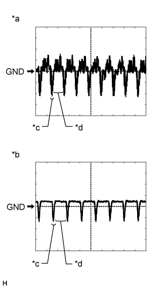
Reference (Oscilloscope waveform):
Waveform 1
| Item | Content |
| Measurement Terminal | F78-6 (VV+) - F77-12 (GND1) |
| Measurement Setting | 200 mV/DIV., 10 μs/DIV. |
| Condition | DVD is playing |
- HINT:
- The video waveform changes according to the image input from the multi-media module receiver assembly to the multi-display assembly, but the synchronization signal does not change.
| *a | Synchronization Signal |
| *b | Video Waveform |
Reference (Oscilloscope waveform):
Waveform 2 (camera lens is not covered, displaying an image)
| Item | Content |
| Measurement terminal | F77-18 (V+) - F77-19 (V-) |
| Measurement setting | 200 mV/DIV., 50 μs/DIV. |
| Condition | Engine switch on (IG), reverse (R) selected, camera lens is not covered, displaying an image |
- HINT:
- The video waveform changes according to the image from the rear television camera assembly.
Waveform 3 (camera lens is covered, blacking out the screen)
| Item | Content |
| Measurement terminal | F77-18 (V+) - F77-19 (V-) |
| Measurement setting | 200 mV/DIV., 50 μs/DIV. |
| Condition | Engine switch on (IG), reverse (R) selected, camera lens is covered, blacking out screen |
- HINT:
- The video waveform changes according to the image from the rear television camera assembly.
| *a | Waveform 1 (camera lens is not covered, displaying an image) |
| *b | Waveform 2 (camera lens is covered, blacking out the screen) |
| *c | Synchronization Signal |
| *d | Video Waveform |
| MULTI-DISPLAY ASSEMBLY |
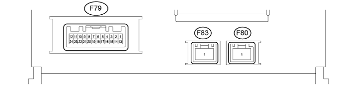
| Terminal No. (Symbol) | Wiring Color | Terminal Description | Condition | Specified Condition |
| F79-2 (ILL) - F79-13 (GND1) | G - BR | Illumination signal | Engine switch on (IG), light control switch off → tail or head position | Below 1 V → 11 to 14 V |
| F79-3 (UPSW) | P | UART communication signal | - | - |
| F79-4 (UIND) | R | UART communication signal | - | - |
| F79-7 (TX+) | B | AVC-LAN communication signal | - | - |
| F79-11 (VMTI) - F79-13 (GND1) | V - BR | Visual mute signal | When image on display switches | 3.5 V or higher → Below 1 V → 3.5 V or higher |
| F79-12 (+B2) - F79-13 (GND1) | R - BR | Power source | Always | 11 to 14 V |
| F79-13 (GND1) - Body ground | BR - Body ground | Ground | Always | Below 1 Ω |
| F79-14 (ILL-) - F79-13 (GND1) | W - BR | Illumination signal | Engine switch on (IG), light control switch off → tail or head position | Below 1 V → Pulse generation |
| F79-19 (TX-) | W | AVC-LAN communication signal | - | - |
| F79-23 (IG) - F79-13 (GND1) | G - BR | Power source (IG) | Engine switch on (IG) | 11 to 14 V |
| Engine switch off | Below 1 V | |||
| F79-24 (ACC) - F79-13 (GND1) | GR - BR | Power source (ACC) | Engine switch on (ACC) | 11 to 14 V |
| Engine switch off | Below 1 V |
| STEREO COMPONENT AMPLIFIER ASSEMBLY () |
| TELEVISION DISPLAY ASSEMBLY () |