DESCRIPTION
WIRING DIAGRAM
INSPECTION PROCEDURE
CHECK FOR DTC
CHECK HARNESS AND CONNECTOR (NO. 1 ULTRASONIC SENSOR [RR SENSOR] - PARKING ASSIST ECU)
CHECK HARNESS AND CONNECTOR (NO. 1 ULTRASONIC SENSOR [RR SENSOR] - NO. 1 ULTRASONIC SENSOR [RRC SENSOR])
CHECK HARNESS AND CONNECTOR (NO. 1 ULTRASONIC SENSOR [RRC SENSOR] - NO. 1 ULTRASONIC SENSOR [RLC SENSOR])
CHECK HARNESS AND CONNECTOR (NO. 1 ULTRASONIC SENSOR [RLC SENSOR] - NO. 1 ULTRASONIC SENSOR [RL SENSOR])
CHECK PARKING ASSIST ECU
CHECK FOR DTC
REPLACE NO. 1 ULTRASONIC SENSOR (RR SENSOR)
CHECK FOR DTC
REPLACE NO. 1 ULTRASONIC SENSOR (RL SENSOR)
CHECK FOR DTC
REPLACE NO. 1 ULTRASONIC SENSOR (RRC SENSOR)
CHECK FOR DTC
REPLACE NO. 1 ULTRASONIC SENSOR (RLC SENSOR)
CHECK FOR DTC
CHECK HARNESS AND CONNECTOR (NO. 1 ULTRASONIC SENSOR [RR SENSOR] - CLEARANCE WARNING ECU ASSEMBLY)
CHECK HARNESS AND CONNECTOR (NO. 1 ULTRASONIC SENSOR [RR SENSOR] - NO. 1 ULTRASONIC SENSOR [RRC SENSOR])
CHECK HARNESS AND CONNECTOR (NO. 1 ULTRASONIC SENSOR [RRC SENSOR] - NO. 1 ULTRASONIC SENSOR [RLC SENSOR])
CHECK HARNESS AND CONNECTOR (NO. 1 ULTRASONIC SENSOR [RLC SENSOR] - NO. 1 ULTRASONIC SENSOR [RL SENSOR])
CHECK CLEARANCE WARNING ECU ASSEMBLY
CHECK FOR DTC
REPLACE NO. 1 ULTRASONIC SENSOR (RR SENSOR)
CHECK FOR DTC
REPLACE NO. 1 ULTRASONIC SENSOR (RL SENSOR)
CHECK FOR DTC
REPLACE NO. 1 ULTRASONIC SENSOR (RRC SENSOR)
CHECK FOR DTC
REPLACE NO. 1 ULTRASONIC SENSOR (RLC SENSOR)
CHECK FOR DTC
DTC C1AED Rear Sensor Communication Malfunction
DESCRIPTION
This DTC is stored when there is an open or short circuit in the communication line between the rear sensors and the ECU, or when there is a malfunction in a rear sensor.
| DTC Code | DTC Detection Condition | Trouble Area |
| C1AED | An open or short circuit in the communication line between the rear sensors and ECU or a malfunction in a rear sensor during initialization mode after the engine switch is turned on (IG). | No. 1 ultrasonic sensor (rear side)
Harness or connector
Parking assist ECU*1
Clearance warning ECU assembly*2
|
*1: w/ Side Monitor System
*2: w/o Side Monitor System
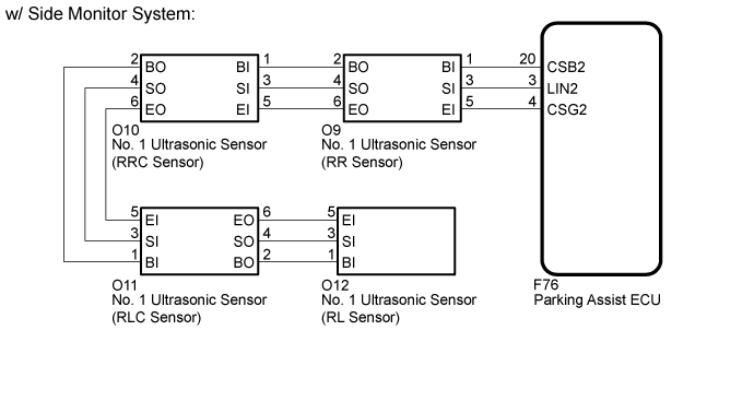
WIRING DIAGRAM

INSPECTION PROCEDURE
Check for DTCs ().
Result| Result | Proceed to |
| DTC C1AED is output (w/ Side Monitor System) | A |
| DTC C1AED is output (w/o Side Monitor System) | B |
| DTC C1AED is not output | C |
| |
|
| | USE SIMULATION METHOD TO CHECK ()
|
|
|
| 2.CHECK HARNESS AND CONNECTOR (NO. 1 ULTRASONIC SENSOR [RR SENSOR] - PARKING ASSIST ECU) |
Disconnect the O9 No. 1 ultrasonic sensor (RR sensor) connector.
Disconnect the F76 parking assist ECU connector.
Measure the resistance according to the value(s) in the table below.
- Standard Resistance:
| Tester Connection | Condition | Specified Condition |
| O9-1 (BI) - F76-20 (CGB2) | Always | Below 1 Ω |
| O9-3 (SI) - F76-3 (LIN2) | Always | Below 1 Ω |
| O9-5 (EI) - F76-4 (CSG2) | Always | Below 1 Ω |
| O9-1 (BI) - Body ground | Always | 10 kΩ or higher |
| O9-3 (SI) - Body ground | Always | 10 kΩ or higher |
| O9-5 (EI) - Body ground | Always | 10 kΩ or higher |
| | REPAIR OR REPLACE HARNESS OR CONNECTOR |
|
|
| 3.CHECK HARNESS AND CONNECTOR (NO. 1 ULTRASONIC SENSOR [RR SENSOR] - NO. 1 ULTRASONIC SENSOR [RRC SENSOR]) |
Disconnect the O9 No. 1 ultrasonic sensor (RR sensor) connector.
Disconnect the O10 No. 1 ultrasonic sensor (RRC sensor) connector.
Measure the resistance according to the value(s) in the table below.
- Standard Resistance:
| Tester Connection | Condition | Specified Condition |
| O9-2 (BO) - O10-1 (BI) | Always | Below 1 Ω |
| O9-4 (SO) - O10-3 (SI) | Always | Below 1 Ω |
| O9-6 (EO) - O10-5 (EI) | Always | Below 1 Ω |
| O9-2 (BO) - Body ground | Always | 10 kΩ or higher |
| O9-4 (SO) - Body ground | Always | 10 kΩ or higher |
| O9-6 (EO) - Body ground | Always | 10 kΩ or higher |
| | REPAIR OR REPLACE HARNESS OR CONNECTOR |
|
|
| 4.CHECK HARNESS AND CONNECTOR (NO. 1 ULTRASONIC SENSOR [RRC SENSOR] - NO. 1 ULTRASONIC SENSOR [RLC SENSOR]) |
Disconnect the O10 No. 1 ultrasonic sensor (RRC sensor) connector.
Disconnect the O11 No. 1 ultrasonic sensor (RLC sensor) connector.
Measure the resistance according to the value(s) in the table below.
- Standard Resistance:
| Tester Connection | Condition | Specified Condition |
| O10-2 (BO) - O11-1 (BI) | Always | Below 1 Ω |
| O10-4 (SO) - O11-3 (SI) | Always | Below 1 Ω |
| O10-6 (EO) - O11-5 (EI) | Always | Below 1 Ω |
| O10-2 (BO) - Body ground | Always | 10 kΩ or higher |
| O10-4 (SO) - Body ground | Always | 10 kΩ or higher |
| O10-6 (EO) - Body ground | Always | 10 kΩ or higher |
| | REPAIR OR REPLACE HARNESS OR CONNECTOR |
|
|
| 5.CHECK HARNESS AND CONNECTOR (NO. 1 ULTRASONIC SENSOR [RLC SENSOR] - NO. 1 ULTRASONIC SENSOR [RL SENSOR]) |
Disconnect the O11 No. 1 ultrasonic sensor (RLC sensor) connector.
Disconnect the O12 No. 1 ultrasonic sensor (RL sensor) connector.
Measure the resistance according to the value(s) in the table below.
- Standard Resistance:
| Tester Connection | Condition | Specified Condition |
| O11-2 (BO) - O12-1 (BI) | Always | Below 1 Ω |
| O11-4 (SO) - O12-3 (SI) | Always | Below 1 Ω |
| O11-6 (EO) - O12-5 (EI) | Always | Below 1 Ω |
| O11-2 (BO) - Body ground | Always | 10 kΩ or higher |
| O11-4 (SO) - Body ground | Always | 10 kΩ or higher |
| O11-6 (EO) - Body ground | Always | 10 kΩ or higher |
| | REPAIR OR REPLACE HARNESS OR CONNECTOR |
|
|
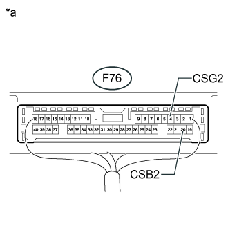
| 6.CHECK PARKING ASSIST ECU |
Measure the voltage according to the value(s) in the table below.
- Standard Voltage:
| Tester Connection | Switch Condition | Specified Condition |
| F76-4 (CGB2) - Body ground | Engine switch on (IG) | 7.2 to 8.8 V |
Measure the resistance according to the value(s) in the table below.
- Standard Resistance:
| Tester Connection | Condition | Specified Condition |
| F76-20 (CSG2) - Body ground | Always | Below 1 Ω |
Text in Illustration| *a | Component with harness connected
(Parking Assist ECU) |
| | REPLACE PARKING ASSIST ECU ()
|
|
|
Check for DTCs ().
Result| Result | Proceed to |
| DTC C1AED is output and multi-information display indicates open circuit (Rear Left, Rear Center and Rear Right) | A |
| DTC C1AED is output and multi-information display indicates open circuit (Rear Left and Rear Center) | B |
| DTC C1AED is not output | C |
| |
|
| | USE SIMULATION METHOD TO CHECK ()
|
|
|
| 8.REPLACE NO. 1 ULTRASONIC SENSOR (RR SENSOR) |
Replace the No. 1 ultrasonic sensor (RR sensor) with a normally functioning one ().
Check for DTCs ().
Result| Result | Proceed to |
| DTC C1AED is output and multi-information display indicates open circuit (Rear Left, Rear Center and Rear Right) | A |
| DTC C1AED is output and multi-information display indicates open circuit (Rear Left and Rear Center) | B |
| DTC C1AED is not output | C |
| |
|
| | END (NO. 1 ULTRASONIC SENSOR [RR SENSOR] IS DEFECTIVE) |
|
|
| 10.REPLACE NO. 1 ULTRASONIC SENSOR (RL SENSOR) |
Replace the No. 1 ultrasonic sensor (RL sensor) with a normally functioning one ().
Check for DTCs ().
Result| Result | Proceed to |
| DTC C1AED is output and multi-information display indicates open circuit (Rear Left and Rear Center) | A |
| DTC C1AED is output and multi-information display indicates open circuit (Rear Left, Rear Center and Rear Right) | B |
| DTC C1AED is not output | C |
| | REPLACE PARKING ASSIST ECU ()
|
|
|
| | END (NO. 1 ULTRASONIC SENSOR [RL SENSOR] IS DEFECTIVE) |
|
|
| 12.REPLACE NO. 1 ULTRASONIC SENSOR (RRC SENSOR) |
Replace the No. 1 ultrasonic sensor (RRC sensor) with a normally functioning one ().
Check for DTCs ().
- OK:
- DTC C1AED is not output
| OK | |
| |
| END (NO. 1 ULTRASONIC SENSOR [RRC SENSOR] IS DEFECTIVE) |
|
| 14.REPLACE NO. 1 ULTRASONIC SENSOR (RLC SENSOR) |
Replace the No. 1 ultrasonic sensor (RLC sensor) with a normally functioning one ().
Check for DTCs ().
- OK:
- DTC C1AED is not output
| | REPLACE PARKING ASSIST ECU ()
|
|
|
| OK | |
| |
| END (NO. 1 ULTRASONIC SENSOR [RLC SENSOR] IS DEFECTIVE) |
|
| 16.CHECK HARNESS AND CONNECTOR (NO. 1 ULTRASONIC SENSOR [RR SENSOR] - CLEARANCE WARNING ECU ASSEMBLY) |
Disconnect the O9 No. 1 ultrasonic sensor (RR sensor) connector.
Disconnect the F12 clearance warning ECU assembly connector.
Measure the resistance according to the value(s) in the table below.
- Standard Resistance:
| Tester Connection | Condition | Specified Condition |
| O9-1 (BI) - F12-7 (CGB2) | Always | Below 1 Ω |
| O9-3 (SI) - F12-24 (LIN2) | Always | Below 1 Ω |
| O9-5 (EI) - F12-18 (CSG2) | Always | Below 1 Ω |
| O9-1 (BI) - Body ground | Always | 10 kΩ or higher |
| O9-3 (SI) - Body ground | Always | 10 kΩ or higher |
| O9-5 (EI) - Body ground | Always | 10 kΩ or higher |
| | REPAIR OR REPLACE HARNESS OR CONNECTOR |
|
|
| 17.CHECK HARNESS AND CONNECTOR (NO. 1 ULTRASONIC SENSOR [RR SENSOR] - NO. 1 ULTRASONIC SENSOR [RRC SENSOR]) |
Disconnect the O9 No. 1 ultrasonic sensor (RR sensor) connector.
Disconnect the O10 No. 1 ultrasonic sensor (RRC sensor) connector.
Measure the resistance according to the value(s) in the table below.
- Standard Resistance:
| Tester Connection | Condition | Specified Condition |
| O9-2 (BO) - O10-1 (BI) | Always | Below 1 Ω |
| O9-4 (SO) - O10-3 (SI) | Always | Below 1 Ω |
| O9-6 (EO) - O10-5 (EI) | Always | Below 1 Ω |
| O9-2 (BO) - Body ground | Always | 10 kΩ or higher |
| O9-4 (SO) - Body ground | Always | 10 kΩ or higher |
| O9-6 (EO) - Body ground | Always | 10 kΩ or higher |
| | REPAIR OR REPLACE HARNESS OR CONNECTOR |
|
|
| 18.CHECK HARNESS AND CONNECTOR (NO. 1 ULTRASONIC SENSOR [RRC SENSOR] - NO. 1 ULTRASONIC SENSOR [RLC SENSOR]) |
Disconnect the O10 No. 1 ultrasonic sensor (RRC sensor) connector.
Disconnect the O11 No. 1 ultrasonic sensor (RLC sensor) connector.
Measure the resistance according to the value(s) in the table below.
- Standard Resistance:
| Tester Connection | Condition | Specified Condition |
| O10-2 (BO) - O11-1 (BI) | Always | Below 1 Ω |
| O10-4 (SO) - O11-3 (SI) | Always | Below 1 Ω |
| O10-6 (EO) - O11-5 (EI) | Always | Below 1 Ω |
| O10-2 (BO) - Body ground | Always | 10 kΩ or higher |
| O10-4 (SO) - Body ground | Always | 10 kΩ or higher |
| O10-6 (EO) - Body ground | Always | 10 kΩ or higher |
| | REPAIR OR REPLACE HARNESS OR CONNECTOR |
|
|
| 19.CHECK HARNESS AND CONNECTOR (NO. 1 ULTRASONIC SENSOR [RLC SENSOR] - NO. 1 ULTRASONIC SENSOR [RL SENSOR]) |
Disconnect the O11 No. 1 ultrasonic sensor (RLC sensor) connector.
Disconnect the O12 No. 1 ultrasonic sensor (RL sensor) connector.
Measure the resistance according to the value(s) in the table below.
- Standard Resistance:
| Tester Connection | Condition | Specified Condition |
| O11-2 (BO) - O12-1 (BI) | Always | Below 1 Ω |
| O11-4 (SO) - O12-3 (SI) | Always | Below 1 Ω |
| O11-6 (EO) - O12-5 (EI) | Always | Below 1 Ω |
| O11-2 (BO) - Body ground | Always | 10 kΩ or higher |
| O11-4 (SO) - Body ground | Always | 10 kΩ or higher |
| O11-6 (EO) - Body ground | Always | 10 kΩ or higher |
| | REPAIR OR REPLACE HARNESS OR CONNECTOR |
|
|
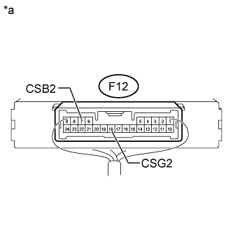
| 20.CHECK CLEARANCE WARNING ECU ASSEMBLY |
Measure the voltage according to the value(s) in the table below.
- Standard Voltage:
| Tester Connection | Switch Condition | Specified Condition |
| F12-7 (CGB2) - Body ground | Engine switch on (IG) | 7.2 to 8.8 V |
Measure the resistance according to the value(s) in the table below.
- Standard Resistance:
| Tester Connection | Condition | Specified Condition |
| F12-18 (CSG2) - Body ground | Always | Below 1 Ω |
Text in Illustration| *a | Component with harness connected
(Clearance Warning ECU Assembly) |
| | REPLACE CLEARANCE WARNING ECU ASSEMBLY ()
|
|
|
Check for DTCs ().
Result| Result | Proceed to |
| DTC C1AED is output and multi-information display indicates open circuit (Rear Left, Rear Center and Rear Right) | A |
| DTC C1AED is output and multi-information display indicates open circuit (Rear Left and Rear Center) | B |
| DTC C1AED is not output | C |
| |
|
| | USE SIMULATION METHOD TO CHECK ()
|
|
|
| 22.REPLACE NO. 1 ULTRASONIC SENSOR (RR SENSOR) |
Replace the No. 1 ultrasonic sensor (RR sensor) with a normally functioning one ().
Check for DTCs ().
Result| Result | Proceed to |
| DTC C1AED is output and multi-information display indicates open circuit (Rear Left, Rear Center and Rear Right) | A |
| DTC C1AED is output and multi-information display indicates open circuit (Rear Left and Rear Center) | B |
| DTC C1AED is not output | C |
| |
|
| | END (NO. 1 ULTRASONIC SENSOR [RR SENSOR] IS DEFECTIVE) |
|
|
| 24.REPLACE NO. 1 ULTRASONIC SENSOR (RL SENSOR) |
Replace the No. 1 ultrasonic sensor (RL sensor) with a normally functioning one ().
Check for DTCs ().
Result| Result | Proceed to |
| DTC C1AED is output and multi-information display indicates open circuit (Rear Left and Rear Center) | A |
| DTC C1AED is output and multi-information display indicates open circuit (Rear Left, Rear Center and Rear Right) | B |
| DTC C1AED is not output | C |
| | REPLACE CLEARANCE WARNING ECU ASSEMBLY ()
|
|
|
| | END (NO. 1 ULTRASONIC SENSOR [RL SENSOR] IS DEFECTIVE) |
|
|
| 26.REPLACE NO. 1 ULTRASONIC SENSOR (RRC SENSOR) |
Replace the No. 1 ultrasonic sensor (RRC sensor) with a normally functioning one ().
Check for DTCs ().
- OK:
- DTC C1AED is not output
| OK | |
| |
| END (NO. 1 ULTRASONIC SENSOR [RRC SENSOR] IS DEFECTIVE) |
|
| 28.REPLACE NO. 1 ULTRASONIC SENSOR (RLC SENSOR) |
Replace the No. 1 ultrasonic sensor (RLC sensor) with a normally functioning one ().
Check for DTCs ().
- OK:
- DTC C1AED is not output
| | REPLACE CLEARANCE WARNING ECU ASSEMBLY ()
|
|
|
| OK | |
| |
| END (NO. 1 ULTRASONIC SENSOR [RLC SENSOR] IS DEFECTIVE) |
|