Dtc B15F9 Uart Communication Malfunction(For A/C)
DESCRIPTION
WIRING DIAGRAM
INSPECTION PROCEDURE
CLEAR DTC
CHECK DTC
CHECK HARNESS AND CONNECTOR (MULTI-MEDIA MODULE RECEIVER ASSEMBLY - MULTI-DISPLAY ASSEMBLY)
REPLACE MULTI-DISPLAY ASSEMBLY
CLEAR DTC
CHECK DTC
DTC B15F9 UART Communication Malfunction(for A/C)
DESCRIPTION
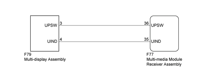
The multi-media module receiver assembly and multi-display assembly are connected by the UART communication line.
When a UART communication error occurs between the multi-media module receiver assembly and multi-display assembly, these DTCs will be stored.
| DTC Code | DTC Detection Condition | Trouble Area |
| B15F9 |
Multi-display for air conditioning switch operation signal input malfunction. |
Multi-display assembly
Multi-media module receiver assembly
Harness or connector
|
WIRING DIAGRAM
INSPECTION PROCEDURE
Recheck for DTCs and check if the same DTC is output again ().
| OK | |
| |
| USE SIMULATION METHOD TO CHECK ()
|
|
| 3.CHECK HARNESS AND CONNECTOR (MULTI-MEDIA MODULE RECEIVER ASSEMBLY - MULTI-DISPLAY ASSEMBLY) |
Disconnect the F77 multi-media module receiver assembly connector.
Disconnect the F79 multi-display assembly connector.
Measure the resistance according to the value(s) in the table below.
- Standard Resistance:
| Tester Connection | Condition | Specified Condition |
| F77-36 (UPSW) - F79-3 (UPSW) | Always | Below 1 Ω |
| F77-35 (UIND) - F79-4 (UIND) | Always | Below 1 Ω |
| F77-36 (UPSW) - Body ground | Always | 10 kΩ or higher |
| F77-35 (UIND) - Body ground | Always | 10 kΩ or higher |
| | REPAIR OR REPLACE HARNESS OR CONNECTOR |
|
|
| 4.REPLACE MULTI-DISPLAY ASSEMBLY |
Replace the multi-display assembly with a new or normally functioning one ().
Recheck for DTCs and check if the same DTC is output again ().
| | REPLACE MULTI-MEDIA MODULE RECEIVER ASSEMBLY ()
|
|
|
| OK | |
| |
| END (MULTI-DISPLAY ASSEMBLY IS DEFECTIVE) |
|