Audio And Visual System (W/O Navigation System) - Avc-Lan Circuit
DESCRIPTION
INSPECTION PROCEDURE
INSPECT RADIO RECEIVER ASSEMBLY
CHECK HARNESS AND CONNECTOR (AVC-LAN CIRCUIT)
INSPECT MALFUNCTIONING PARTS
AUDIO AND VISUAL SYSTEM (w/o Navigation System) - AVC-LAN Circuit
DESCRIPTION
Each audio system component connected to the AVC-LAN (communication bus) transfers the switch signals by the audio visual communication local area network.
If a short to +B or short to ground occurs in this AVC-LAN, the audio system will not function normally as communication is stopped.
INSPECTION PROCEDURE
| 1.INSPECT RADIO RECEIVER ASSEMBLY |
Disconnect the F1 and F55 radio receiver assembly connectors.
Measure the resistance according to the value(s) in the table below.
- Standard Resistance:
| Tester Connection | Condition | Specified Condition |
| F1-5 (ATX+) - F1-15 (ATX-) | Always | 60 to 80 Ω |
| F55-9 (TXM+) - F55-10 (TXM-) | Always | 60 to 80 Ω |
Text in Illustration| *1 | Component without harness connected
(Radio Receiver Assembly) |
| *2 | Component without harness connected
(Radio Receiver Assembly) |
| | REPLACE RADIO RECEIVER ASSEMBLY ()
|
|
|
| 2.CHECK HARNESS AND CONNECTOR (AVC-LAN CIRCUIT) |
- For details of the connectors, refer to Terminals of ECU ().
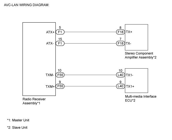
Referring to the following AVC-LAN wiring diagram, check all AVC-LAN circuits.
Disconnect all connectors in all AVC-LAN circuits.
Check for an open or short in all AVC-LAN circuits.
- OK:
- There is no open or short circuit.
| | REPAIR OR REPLACE HARNESS OR CONNECTOR |
|
|
| 3.INSPECT MALFUNCTIONING PARTS |
Disconnect and reconnect each slave unit one by one until the master unit returns to normal operation.
Check all slave units.
When disconnecting a slave unit causes the master unit to return to normal operation, this indicates that the slave unit is malfunctioning. Replace the malfunctioning slave unit.
- OK:
- Master unit returns to normal operation.
| | PROCEED TO NEXT SUSPECTED AREA SHOWN IN PROBLEM SYMPTOMS TABLE ()
|
|
|
| OK | |
| |
| REPLACE MALFUNCTIONING PARTS |
|
