Land Cruiser URJ200 URJ202 GRJ200 VDJ200 - AUDIO / VIDEO
CHECK HARNESS AND CONNECTOR (MULTI-MEDIA INTERFACE ECU - NO. 1 STEREO JACK ADAPTER)
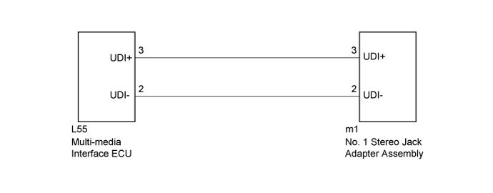
AUDIO AND VISUAL SYSTEM (w/o Navigation System) - Sound Signal Circuit between Multi-media Interface ECU and Stereo Jack Adapter
DESCRIPTION
The No. 1 stereo jack adapter assembly sends the sound data signal of an external device to the multi-media interface ECU through this circuit.
WIRING DIAGRAM
INSPECTION PROCEDURE
| 1.CHECK HARNESS AND CONNECTOR (MULTI-MEDIA INTERFACE ECU - NO. 1 STEREO JACK ADAPTER) |
Disconnect the L55 multi-media interface ECU connector.
Disconnect the m1 No. 1 stereo jack adapter assembly connector.
Measure the resistance according to the value(s) in the table below.
- Standard Resistance:
Tester Connection Condition Specified Condition m1-3 (UDI+) - L55-3 (UDI+) Always Below 1 Ω m1-2 (UDI-) - L55-2 (UDI-) Always Below 1 Ω m1-3 (UDI+) - Body ground Always 10 kΩ or higher m1-2 (UDI-) - Body ground Always 10 kΩ or higher
|
| ||||
| OK | ||
| ||