1. INSTALL FLYWHEEL RING GEAR (for Manual Transmission)

-
Using a torch, heat the ring gear evenly to approximately 200°C (392°F).
NOTICE:
Be careful not to overheat the ring gear.
-
Using a brass bar, tap the ring gear onto the flywheel with its chamfered gear teeth facing the block.
NOTICE:
After installing, allow the ring gear to cool before handling.
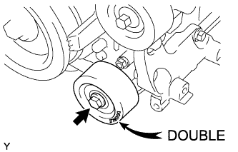
2. INSTALL NO. 1 IDLER PULLEY SUB-ASSEMBLY
-
Install the No. 1 idler pulley with the bolt.
Torque:
54 N*m{ 551 kgf*cm , 40 ft.*lbf }
HINT:
"DOUBLE" is marked on the No. 1 idler pulley to distinguish it from the No. 2 idler pulley.
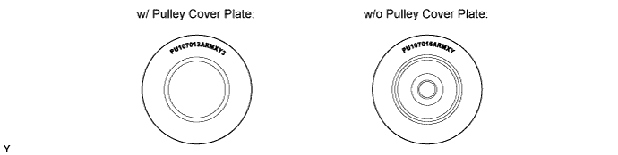
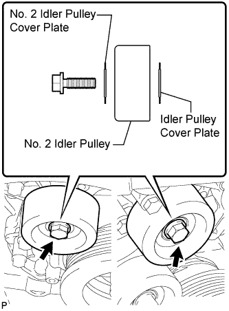
3. INSTALL NO. 2 IDLER PULLEY SUB-ASSEMBLY
-
w/ Pulley Cover Plate:
-
Install the idler pulley cover plate, idler pulley and No. 2 idler pulley cover plate with the bolt.
Torque:
54 N*m{ 551 kgf*cm , 40 ft.*lbf }
NOTICE:
If it is necessary to replace the pulley or either plate, replace the No. 2 idler pulley cover plate, No. 2 idler pulley and idler pulley cover plate as a set with new parts.
-
-
w/o Pulley Cover Plate: Install the 2 No. 2 idler pulleys with the 2 bolts.
Torque:
54 N*m{ 551 kgf*cm , 40 ft.*lbf }
4. INSTALL FRONT NO. 1 ENGINE MOUNTING BRACKET LH
-
Install the engine mounting bracket with the 3 bolts.
Torque:
43 N*m{ 438 kgf*cm , 32 ft.*lbf }
5. INSTALL FRONT NO. 1 ENGINE MOUNTING BRACKET RH
-
Install the engine mounting RH with the 4 bolts.
Torque:
43 N*m{ 438 kgf*cm , 32 ft.*lbf }
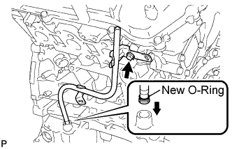
6. INSTALL ENGINE OIL LEVEL DIPSTICK GUIDE
-
Install a new O-ring to the dipstick guide.
-
Apply a light coat of engine oil to the O-ring.
-
Push the dipstick guide end into the guide hole.
-
Install the dipstick guide with the bolt.
Torque:
9.0 N*m{ 92 kgf*cm , 80 in.*lbf }
7. INSTALL V-RIBBED BELT TENSIONER ASSEMBLY

-
Temporarily install the V-ribbed belt tensioner with the 5 bolts.
-
Tighten bolt 1 and 2 in numerical order.
Torque:
36 N*m{ 367 kgf*cm , 27 ft.*lbf }
-
Tighten the other bolts.
Torque:
36 N*m{ 367 kgf*cm , 27 ft.*lbf }
Standard Bolt:
Item Length A 70 mm (2.76 in.) B 33 mm (1.30 in.)
8. INSTALL IGNITION COIL ASSEMBLY
-
Install the 6 ignition coils with the 6 bolts.
Torque:
10 N*m{ 102 kgf*cm , 7 ft.*lbf }
9. INSTALL ENGINE WIRE
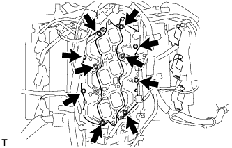
10. INSTALL INTAKE MANIFOLD

-
Set a new gasket on each cylinder head.
NOTICE:
- Align the port holes of the gasket and cylinder head.
- Be careful of the installation direction.
-
Set the intake manifold on the cylinder heads.
-
Install and uniformly tighten the 10 bolts in several passes.
Torque:
26 N*m{ 265 kgf*cm , 19 ft.*lbf }
HINT:
Tighten the inner installation bolts of the intake manifold before tightening the outer bolts.
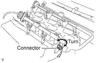
11. INSTALL FUEL INJECTOR

-
Install a new insulator onto each fuel injector.
-
Apply a light coat of spindle oil or gasoline to each new O-ring and install one onto each fuel injector.

-
Install the 6 injectors.
-
While turning each fuel injector left and right, install it onto the fuel delivery pipe.
-
Position the fuel injector connectors facing outward.
-
12. INSTALL FUEL DELIVERY PIPE SUB-ASSEMBLY
-
Place the fuel delivery pipe together with the 6 fuel injectors on the intake manifold.
-
Temporarily install the 6 bolts, which are used to hold the fuel delivery pipe, to the intake manifold.
-
Check that the fuel injectors rotate smoothly.
HINT:
If the fuel injectors do not rotate smoothly, replace the O-ring of any injector that does not rotate smoothly.
-
Position the fuel injector connectors facing outward.
-
Tighten the 6 bolts, which are used to hold the fuel delivery pipe, to the intake manifold.
Torque:
15 N*m{ 153 kgf*cm , 11 ft.*lbf }
-
Connect the 6 fuel injector connectors.
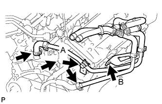
13. CONNECT WATER HOSE SUB-ASSEMBLY (for Automatic Transmission)
-
Connect the heater water by-pass pipe hose to the rear water by-pass joint.
-
Temporarily install the heater water pipe, and then tighten the 2 bolts in the order shown in the illustration.
Torque:
for bolt A:
9.8 N*m{ 100 kgf*cm , 87 in.*lbf }
for bolt B:
13 N*m{ 138 kgf*cm , 10 ft.*lbf }
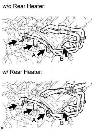
14. CONNECT WATER HOSE SUB-ASSEMBLY (for Manual Transmission)
-
Connect the heater water by-pass pipe hose to the rear water by-pass joint.
-
Temporarily install the heater water pipe, and then tighten the 2 bolts in the order shown in the illustration.
Torque:
for bolt A:
9.8 N*m{ 100 kgf*cm , 87 in.*lbf }
for bolt B:
13 N*m{ 138 kgf*cm , 10 ft.*lbf }
15. CONNECT NO. 1 WATER BY-PASS PIPE (for Automatic Transmission)
-
Connect the water by-pass pipe hoses to the water by-pass pipe and No. 1 water outlet pipe.
16. INSTALL ENGINE COOLANT TEMPERATURE SENSOR
-
Install a new gasket and the engine coolant temperature sensor.
Torque:
20 N*m{ 204 kgf*cm , 15 ft.*lbf }
17. INSTALL OIL PRESSURE SENSOR
-
Apply adhesive to 2 or 3 threads of the oil pressure sensor.
Adhesive:
Toyota Genuine Adhesive 1344, Three Bond 1344 or equivalent
-
Using a 24 mm deep socket wrench, install the oil pressure sensor.
Torque:
15 N*m{ 150 kgf*cm , 11 ft.*lbf }
NOTICE:
Do not start the engine within 1 hour of installation.