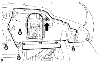
| REMOVE FRONT FENDER SPLASH SHIELD SUB-ASSEMBLY LH |
-
Remove the 3 bolts and screw.
-
Turn the clip indicated by the arrow in the illustration to remove the fender splash shield.
| 2. REMOVE FRONT FENDER SPLASH SHIELD SUB-ASSEMBLY RH |
HINT:
Use the same procedures described for the LH side.
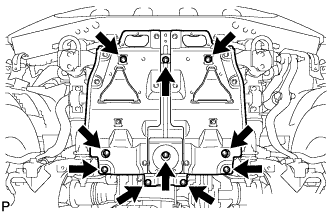
| 3. REMOVE NO. 1 ENGINE UNDER COVER SUB-ASSEMBLY |
-
Remove the 10 bolts and No. 1 engine under cover.
| 4. DRAIN ENGINE COOLANT |
CAUTION:
Do not remove the radiator cap while the engine and radiator are still hot. Pressurized, hot engine coolant and steam may be released and cause serious burns.
-
Loosen the radiator drain cock plug.
HINT:
Collect the coolant in a container and dispose of it according to the regulations in your area.
-
Remove the radiator cap. Then drain the coolant from the radiator.
-
Loosen the 2 cylinder block drain cock plugs. Then drain the coolant from the engine.
-
Tighten the 2 cylinder block drain cock plugs.
Torque:
13 N*m{ 133 kgf*cm , 10 ft.*lbf }
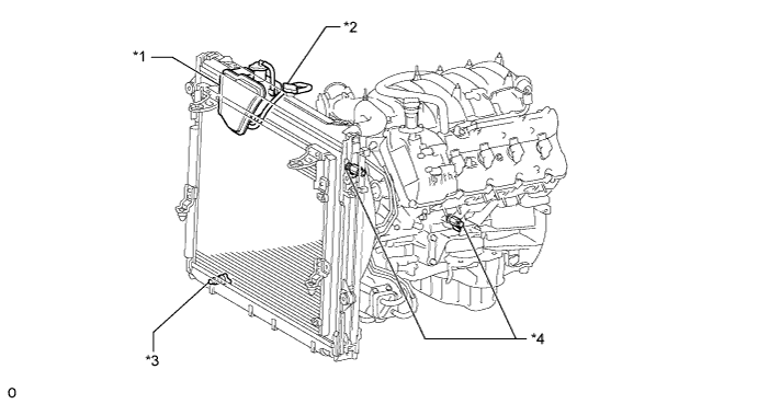
Text in Illustration *1 Radiator Reservoir *2 Radiator Cap *3 Radiator Drain Cock Plug *4 Cylinder Block Drain Cock Plug
-
Tighten the radiator drain cock plug by hand.
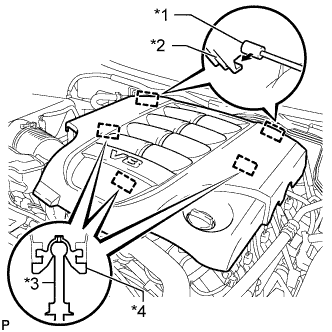
| 5. REMOVE V-BANK COVER SUB-ASSEMBLY |
-
Raise the front of the V-bank cover to detach the 3 pins. Then remove the 2 V-bank cover hooks from the bracket, and remove the V-bank cover.
Text in Illustration *1 Bracket *2 Hook *3 Pin *4 Grommet
| 6. REMOVE NO. 1 RADIATOR HOSE |
| 7. REMOVE FAN SHROUD |
-
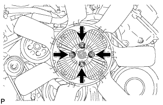
Loosen the 4 nuts holding the fluid coupling fan.
-
Remove the fan and generator V-belt.
-
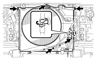
Disconnect the reservoir hose from the upper radiator tank.
-
Detach the claw to open the flexible hose clamp.
-
Remove the 2 bolts and disconnect the oil cooler tube from the fan shroud.
-
Remove the 2 bolts holding the fan shroud.
-
Remove the 4 nuts of the fluid coupling fan, and then remove the shroud together with the coupling fan.
NOTICE:
Be careful not to damage the radiator core.
-
Remove the fan pulley.
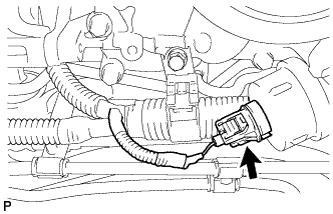
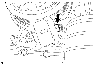
| 8. REMOVE OIL PRESSURE SENDER GAUGE ASSEMBLY |
-
Disconnect the sender gauge connector.
-
Remove the oil pressure sender gauge.
| 9. DISCONNECT COOLER COMPRESSOR ASSEMBLY |
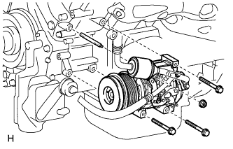
-
Remove the 3 bolts, nut and stud bolt, and disconnect the cooler compressor.
HINT:
It is not necessary to completely remove the compressor. With the hoses connected to the compressor, hang the compressor on the vehicle body with a rope.
| 10. DISCONNECT NO. 2 WATER BY-PASS PIPE SUB-ASSEMBLY |
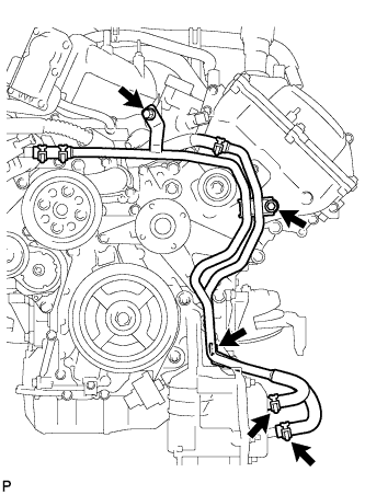
-
Remove the 3 bolts and disconnect the 2 water by-pass hoses from the oil cooler.
| 11. REMOVE NO. 1 OIL COOLER BRACKET |
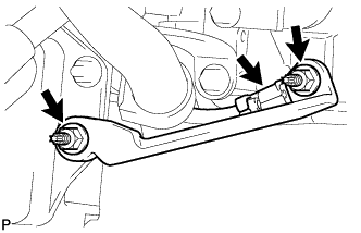
-
Remove the 2 nuts and bracket.
-
Disconnect the ground wire from the cylinder block.
| 12. REMOVE OIL FILTER BRACKET |
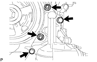
-
Remove the 2 bolts, 2 nuts and filter bracket.
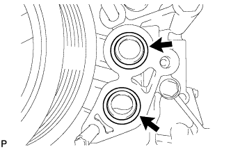
-
Remove the 2 O-rings.
| 13. REMOVE CRANKSHAFT PULLEY |
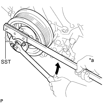
-
Using SST, loosen the crankshaft pulley set bolt until 2 or 3 threads are engaged.
SST
09213-70011 09330-00021
Text in Illustration *a Hold 
Turn
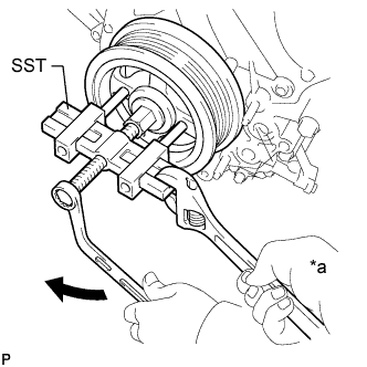
-
Using the pulley set bolt and SST, remove the crankshaft pulley.
SST
09950-50013 (09951-05010,09952-05010,09953-05010,09954-05011)
Text in Illustration *a Hold Turn
| 14. REMOVE CRANKSHAFT TIMING GEAR KEY |
-
Remove the crankshaft timing gear key from the crankshaft.
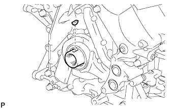
| 15. REMOVE FRONT CRANKSHAFT OIL SEAL |
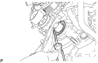
-
Using a screwdriver, pry out the oil seal.
NOTICE:
Do not damage the surface of the oil seal press fit hole and crankshaft.
HINT:
Tape the screwdriver tip before use.