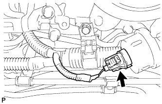
| 1. REMOVE OIL PRESSURE SENDER GAUGE ASSEMBLY |
-
Disconnect the sender gauge connector.
-
Remove the oil pressure sender gauge.
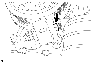
| 2. REMOVE OIL FILTER ELEMENT |
-
Connect a hose with an inside diameter of 15 mm (0.591 in.) to the pipe.
Text in Illustration *1 Pipe *2 Hose
-
Remove the oil filter drain plug.
-
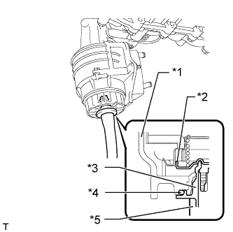
Install the pipe to the oil filter cap.
Text in Illustration *1 Cap *2 Valve *3 Pipe *4 O-Ring *5 Hose NOTICE:
If the O-ring is removed with the drain plug, install the O-ring together with the pipe.
HINT:
Use a container to catch the draining oil.
-
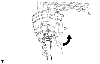
Check that oil is drained from the oil filter. Then disconnect the pipe and remove the O-ring as shown in the illustration.
-
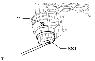
Using SST, remove the oil filter cap.
SST
09228-06501
Text in Illustration *1 Oil Filter Bracket Clip NOTICE:
Do not remove the oil filter bracket clip.
-
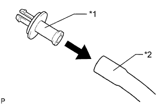
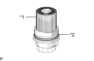
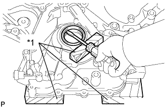
Remove the oil filter element and O-ring from the oil filter cap.
Text in Illustration *1 Oil Filter Element *2 O-Ring NOTICE:
Be sure to remove the cap O-ring by hand, without using any tools, to prevent damage to the cap O-ring groove.
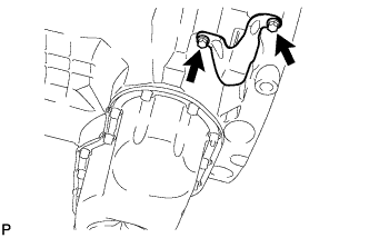
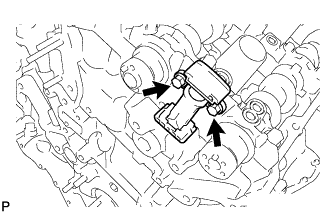
| 3. REMOVE NO. 1 OIL COOLER BRACKET |
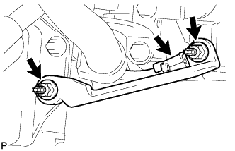
-
Remove the 2 nuts and bracket.
-
Disconnect the ground wire from the cylinder block.
| 4. REMOVE OIL FILTER BRACKET |
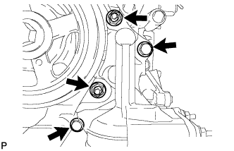
-
Remove the 2 bolts, 2 nuts and filter bracket.
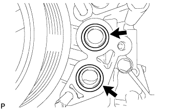
-
Remove the 2 O-rings.
| 5. REMOVE OIL FILLER CAP SUB-ASSEMBLY |
| 6. REMOVE OIL FILLER CAP HOUSING |
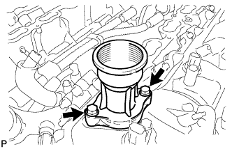
-
Remove the 2 bolts, filler cap housing and gasket.
| 7. REMOVE SPARK PLUG |
-
Using a 16 mm plug wrench, remove the 8 spark plugs.
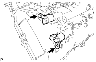
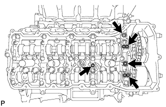
| 8. REMOVE VVT SENSOR |
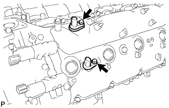
-
LH:
Remove the 2 bolts and 2 VVT sensors.
-
RH:
Remove the 2 bolts and 2 VVT sensors.
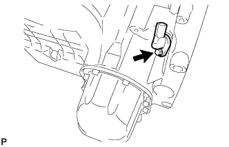
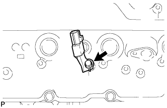
| 9. REMOVE CAMSHAFT POSITION SENSOR |
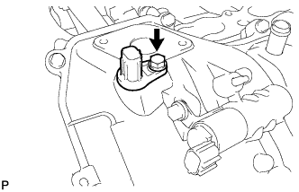
-
Remove the bolt and camshaft position sensor.
| 10. REMOVE CRANK POSITION SENSOR PROTECTOR |
-
Remove the 2 bolts and sensor protector.
| 11. REMOVE CRANKSHAFT POSITION SENSOR |
-
Remove the bolt and crankshaft position sensor.
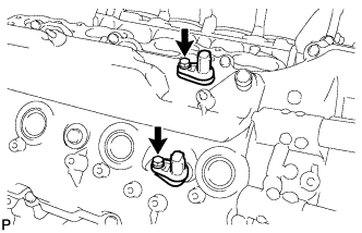
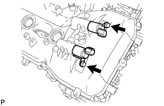
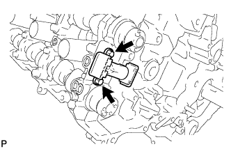
| 12. REMOVE CAMSHAFT OIL CONTROL VALVE ASSEMBLY |
-
LH:
Remove the 2 bolts and 2 oil control valves.
-
RH:
Remove the 2 bolts and 2 oil control valves.
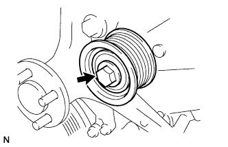
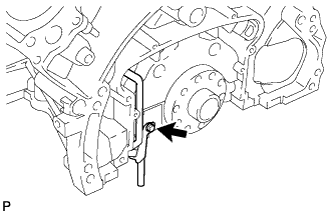
| 13. REMOVE WATER PUMP PULLEY |
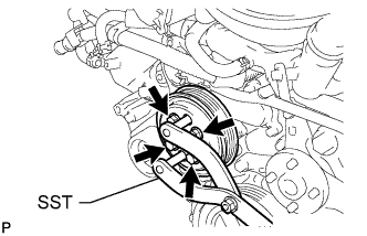
-
Using SST, hold the water pump pulley.
SST
09960-10010 (09962-01000,09963-01000)
-
Remove the 4 bolts and water pump pulley.
| 14. REMOVE NO. 1 IDLER PULLEY SUB-ASSEMBLY |
-
Remove the bolt and idler pulley.
| 15. REMOVE FLUID COUPLING BRACKET |
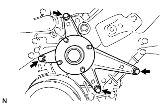
-
Remove the 4 bolts and fluid coupling bracket.
| 16. REMOVE V-RIBBED BELT TENSIONER ASSEMBLY |
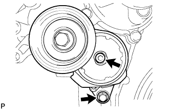
-
Remove the standard bolt, 6 mm hexagon wrench bolt and belt tensioner.
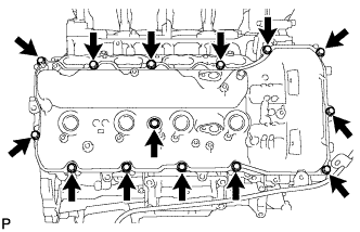
| 17. REMOVE CYLINDER HEAD COVER SUB-ASSEMBLY LH |
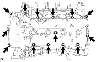
-
Remove the 14 bolts, seal washer, cylinder head cover and gasket.
HINT:
Make sure the removed parts are returned to the same places they were removed from.
-
Remove the 5 gaskets from the camshaft bearing caps (No. 2, No. 3).
| 18. REMOVE CYLINDER HEAD COVER SUB-ASSEMBLY RH |
-
Remove the bolt and noise filter.
-
Remove the 14 bolts, seal washer, cylinder head cover and gasket.
HINT:
Make sure the removed parts are returned to the same places they were removed from.
-
Remove the 5 gaskets from the camshaft bearing caps (No. 1, No. 3).
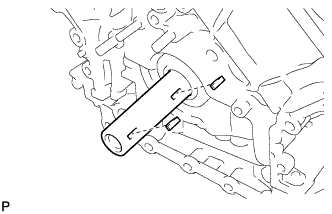
| 19. REMOVE OIL CONTROL VALVE FILTER |
-
LH:
Remove the 3 bolts, cylinder head cover spacer, gasket and filter.
Text in Illustration *1 Cylinder Head Cover Spacer *2 Gasket *3 Filter
-
RH:
Remove the 3 bolts, cylinder head cover spacer, gasket and filter.
Text in Illustration *1 Cylinder Head Cover Spacer *2 Gasket *3 Filter
| 20. REMOVE SPARK PLUG TUBE GASKET |
-
Bend the 4 ventilation baffle plate claws on the cylinder head cover to an angle of 90° or more.
-
Using a screwdriver, pry out the gaskets.
Text in Illustration *1 Tape 
Pry NOTICE:
- Be careful not to damage the cylinder head cover.
- Be careful not to damage the gasket when removing it, as the removed gasket needs to be used when installing a new one.
HINT:
Tape the screwdriver tip before use.
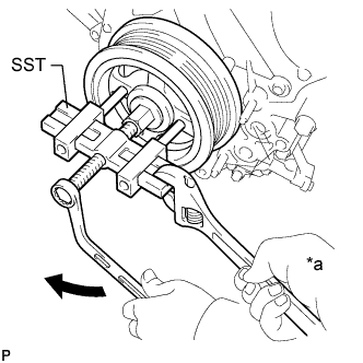
| 21. REMOVE CRANKSHAFT PULLEY |
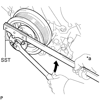
-
Using SST, loosen the crankshaft pulley set bolt until 2 or 3 threads are engaged.
SST
09213-70011 09330-00021
Text in Illustration *a Hold Turn
-
Using the pulley set bolt and SST, remove the crankshaft pulley.
SST
09950-50013 (09951-05010,09952-05010,09953-05010,09954-05011)
Text in Illustration *a Hold Turn
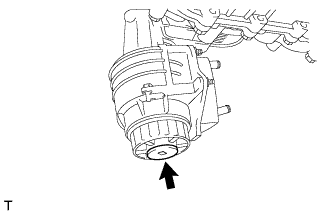
| 22. REMOVE WATER PUMP ASSEMBLY |
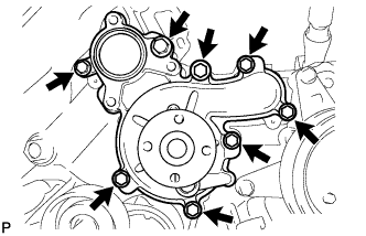
-
Remove the 8 bolts, water pump and gasket.
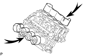
| 23. REMOVE TIMING CHAIN COVER SUB-ASSEMBLY |
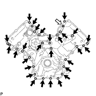
-
Remove the 28 bolts and nut shown in the illustration.
Text in Illustration Bolt 
Nut
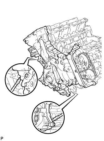
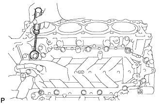
-
Remove the timing chain cover by prying between the timing chain cover and cylinder head or cylinder block with a screwdriver as shown in the illustration.
NOTICE:
Be careful not to damage the contact surfaces of the cylinder head, cylinder block and chain cover.
HINT:
Tape the screwdriver tip before use.
-
Remove the oil pump gasket from the cylinder block.
-
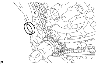
Remove the O-ring from the oil pan.
| 24. REMOVE WATER INLET PIPE |
-
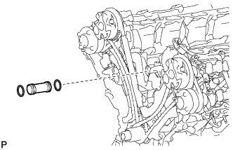
Remove the water inlet pipe.
-
Remove the 2 O-rings from the water inlet pipe.
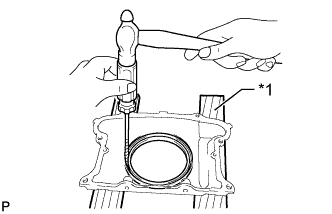
| 25. REMOVE FRONT CRANKSHAFT OIL SEAL |
-
Place the timing chain cover on wooden blocks.
-
Using a screwdriver and wooden block, pry out the oil seal.
Text in Illustration *1 Wooden Block NOTICE:
Do not damage the surface of the oil seal press fit hole.
HINT:
Tape the screwdriver tip before use.
| 26. SET NO. 1 CYLINDER TO TDC/COMPRESSION |
-
Temporarily install the crankshaft pulley bolt.
-
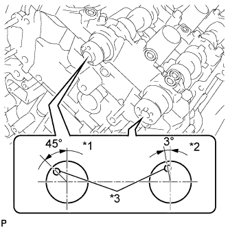
Rotate the crankshaft clockwise so that the timing marks on the crankshaft timing sprocket and camshaft timing gears are as shown in the illustration.
HINT:
If the timing marks do not align, rotate the crankshaft clockwise again and align the timing marks.
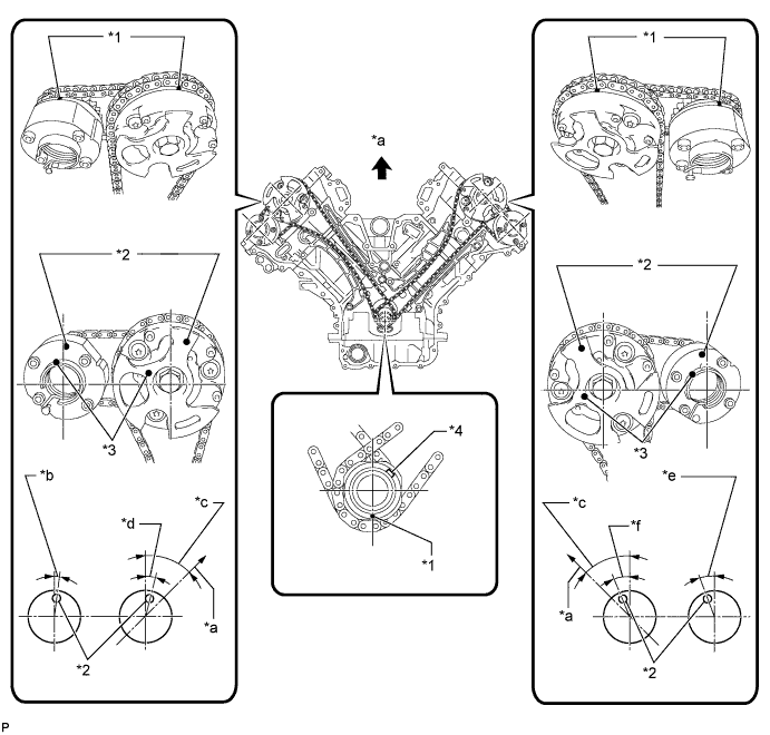
Text in Illustration *1 Timing Mark *2 Timing Mark Position *3 Knock Pin Position *4 Key *a Toward Ceiling *b Approximately 2° *c Approximately 45° *d Approximately 16° *e Approximately 18° *f Approximately 32°
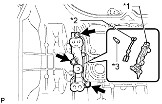
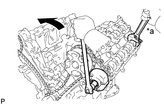
| 27. REMOVE NO. 1 CHAIN TENSIONER ASSEMBLY LH |
-
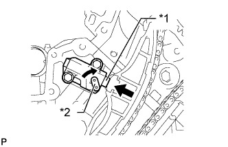
Move the stopper plate clockwise to release the lock, and push the plunger deep into the tensioner.
Text in Illustration *1 Plunger *2 Stopper Plate
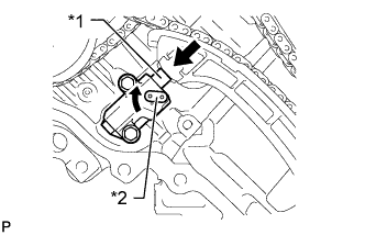
-
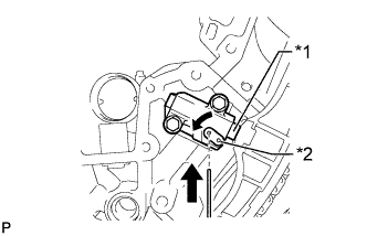
Move the stopper plate counterclockwise to set the lock, and insert a hexagon wrench into the stopper plate hole.
Text in Illustration *1 Plunger *2 Stopper Plate
-
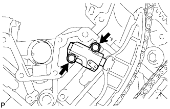
Remove the 2 bolts, chain tensioner and gasket.
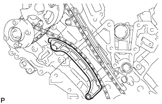
| 28. REMOVE NO. 1 CHAIN TENSIONER SLIPPER LH |
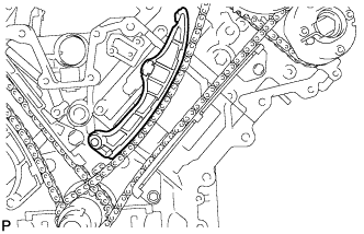
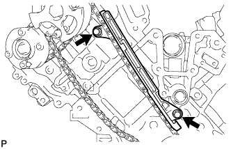
| 29. REMOVE NO. 1 CHAIN VIBRATION DAMPER LH |
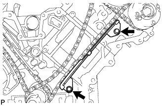
-
Remove the 2 bolts and chain vibration damper.
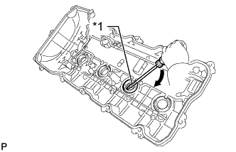
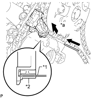
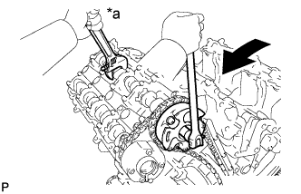
| 30. REMOVE NO. 1 CHAIN SUB-ASSEMBLY LH |
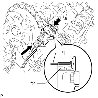
-
While pushing down the No. 3 chain tensioner, insert a pin of 1.0 mm (0.0394 in.) into the hole to fix it in place.
Text in Illustration *1 Pin *2 Plunger *a Push
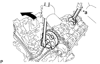
-
Hold the hexagonal portion of the camshaft with a wrench and loosen the bolt.
Text in Illustration *a Hold Turn NOTICE:
- Be careful not to damage the cylinder head with the wrench.
- Do not disassemble the camshaft timing gear.
-
Hold the hexagonal portion of the camshaft with a wrench and loosen the bolt.
Text in Illustration *a Hold Turn NOTICE:
Be careful not to damage the cylinder head with the wrench.
-
Remove the 2 bolts. Then with the No. 1 and No. 2 chains still connected to the gears, remove the camshaft timing gear, camshaft timing exhaust gear and crankshaft timing sprocket LH.
-
Remove the No. 1 and No. 2 chains from the gears.
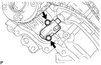
| 31. REMOVE NO. 3 CHAIN TENSIONER ASSEMBLY |
-
Remove the 2 bolts and chain tensioner.
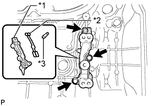
| 32. REMOVE NO. 1 CHAIN TENSIONER ASSEMBLY RH |
-
Move the stopper plate clockwise to release the lock, and push the plunger deep into the tensioner.
Text in Illustration *1 Plunger *2 Stopper Plate
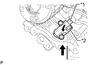
-
Move the stopper plate counterclockwise to set the lock, and insert a hexagon wrench into the stopper plate hole.
Text in Illustration *1 Plunger *2 Stopper Plate
-
Remove the 2 bolts and chain tensioner.
| 33. REMOVE NO. 1 CHAIN TENSIONER SLIPPER RH |
| 34. REMOVE NO. 1 CHAIN VIBRATION DAMPER RH |
-
Remove the 2 bolts and vibration damper.
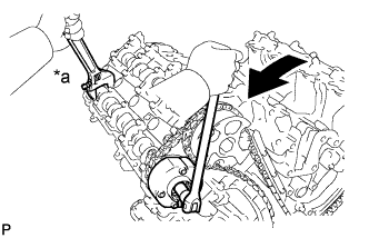
| 35. REMOVE NO. 1 CHAIN SUB-ASSEMBLY RH |
-
While raising up the No. 2 chain tensioner, insert a pin of 1.0 mm (0.0394 in.) into the hole to fix it in place.
Text in Illustration *1 Pin *2 Plunger *a Push
-
Hold the hexagonal portion of the camshaft with a wrench and loosen the bolt.
Text in Illustration *a Hold Turn NOTICE:
- Be careful not to damage the cylinder head with the wrench.
- Do not disassemble the camshaft timing gear.
-
Hold the hexagonal portion of the camshaft with a wrench and loosen the bolt.
Text in Illustration *a Hold Turn NOTICE:
Be careful not to damage the cylinder head with the wrench.
-
Remove the 2 bolts. Then with the No. 1 and No. 2 chains still connected to the gears, remove the camshaft timing gear, camshaft timing exhaust gear and crankshaft timing sprocket RH.
-
Remove the No. 1 and No. 2 chains from the gears.
| 36. REMOVE NO. 2 CHAIN TENSIONER ASSEMBLY |
-
Remove the 2 bolts and chain tensioner.
| 37. REMOVE CRANKSHAFT TIMING GEAR KEY |
-
Using a screwdriver, remove the 2 timing gear keys from the crankshaft.
| 38. REMOVE CAMSHAFT BEARING CAP LH |
-
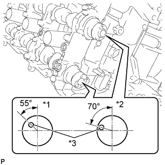
Make sure that the knock pin of the camshaft is positioned as shown in the illustration.
Text in Illustration *1 IN *2 EX *3 Knock Pin
-
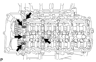
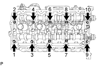
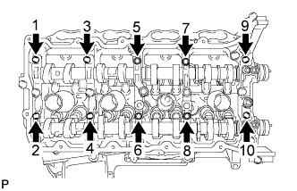
Uniformly loosen and remove the 10 bearing cap bolts in the sequence shown in the illustration.
-
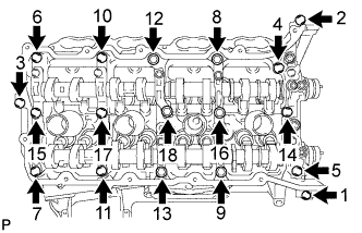
Uniformly loosen and remove the 18 bearing cap bolts in the sequence shown in the illustration.
NOTICE:
Uniformly loosen the bolts while keeping the camshaft level.
-
Remove the 6 bearing caps.
HINT:
Arrange the removed parts in the correct order.
-
Remove the No. 3 and No. 4 camshafts.
| 39. REMOVE CAMSHAFT HOUSING SUB-ASSEMBLY LH |
-
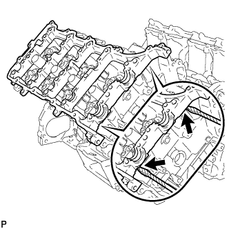
Remove the camshaft housing by prying between the cylinder head and camshaft housing with a screwdriver.
NOTICE:
Be careful not to damage the contact surfaces of the cylinder head and camshaft housing.
HINT:
Tape the screwdriver tip before use.
| 40. REMOVE CAMSHAFT BEARING CAP RH |
-
Make sure that the knock pin of the camshaft is positioned as shown in the illustration.
Text in Illustration *1 EX *2 IN *3 Knock Pin
-
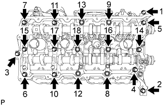
Uniformly loosen and remove the 10 bearing cap bolts in the sequence shown in the illustration.
-
Uniformly loosen and remove the 18 bearing cap bolts in the sequence shown in the illustration.
NOTICE:
Uniformly loosen the bolts while keeping the camshaft level.
-
Remove the 6 bearing caps.
HINT:
Arrange the removed parts in the correct order.
-
Remove the No. 1 and No. 2 camshafts.
| 41. REMOVE CAMSHAFT HOUSING SUB-ASSEMBLY RH |
-
Remove the camshaft housing by prying between the cylinder head and camshaft housing with a screwdriver.
NOTICE:
Be careful not to damage the contact surfaces of the cylinder head and camshaft housing.
HINT:
Tape the screwdriver tip before use.
| 42. REMOVE NO. 1 VALVE ROCKER ARM SUB-ASSEMBLY |
-
Remove the 32 valve rocker arms from the cylinder heads.
HINT:
Arrange the removed parts in the correct order.
| 43. REMOVE VALVE LASH ADJUSTER ASSEMBLY |
-
Remove the 32 valve lash adjusters from the cylinder heads.
HINT:
Arrange the removed parts in the correct order.
| 44. REMOVE VALVE STEM CAP |
-
Remove the 32 valve stem caps from the cylinder heads.
HINT:
Arrange the removed parts in the correct order.
| 45. REMOVE CYLINDER HEAD SUB-ASSEMBLY LH |
-
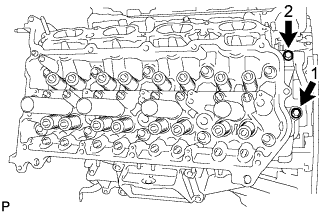
Uniformly loosen and remove the 2 bolts in the sequence shown in the illustration.
-
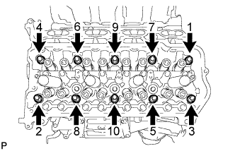
Using a 10 mm bi-hexagon wrench, uniformly loosen the 10 cylinder head bolts in the sequence shown in the illustration. Remove the 10 cylinder head bolts and plate washers.
NOTICE:
- Be careful not to drop washers into the cylinder head.
- Head warpage or cracking could result from removing bolts in an incorrect order.
HINT:
Be sure to arrange the removed parts for each installation position separately.
-
Remove the cylinder head and gasket.
| 46. REMOVE CYLINDER HEAD SUB-ASSEMBLY RH |
-
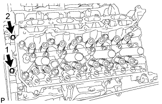
Uniformly loosen and remove the 2 bolts in the sequence shown in the illustration.
-
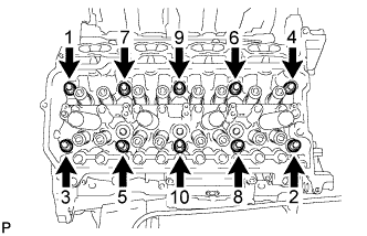
Using a 10 mm bi-hexagon wrench, uniformly loosen the 10 cylinder head bolts in the sequence shown in the illustration. Remove the 10 cylinder head bolts and plate washers.
NOTICE:
- Be careful not to drop washers into the cylinder head.
- Head warpage or cracking could result from removing bolts in an incorrect order.
HINT:
Be sure to arrange the removed parts for each installation position separately.
-
Remove the cylinder head and gasket.
| 47. REMOVE CYLINDER BLOCK WATER JACKET SPACER |
-
Remove the 2 water jacket spacers from the cylinder block.
NOTICE:
Be sure to remove the water jacket spacers. If not, they may fall and become damaged when the cylinder block is inverted.
| 48. REMOVE VENTILATION PIPE GASKET |
-
Using a screwdriver, pry out the ventilation pipe gasket.
HINT:
Tape the screwdriver tip before use.
| 49. REMOVE NO. 1 HEAT EXCHANGER COVER |
-
Remove the 12 bolts and 2 nuts.
Text in Illustration Bolt Nut
-
Remove the heat exchanger by prying between the heat exchanger and cylinder block with a screwdriver.
HINT:
Tape the screwdriver tip before use.
| 50. REMOVE NO. 2 OIL PAN SUB-ASSEMBLY |
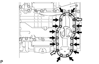
-
Remove the 14 bolts and 2 nuts.
Text in Illustration Bolt Nut
-
Insert the blade of an oil pan seal cutter between the oil pans. Cut through the applied sealer and remove the No. 2 oil pan.
NOTICE:
Be careful not to damage the contact surfaces of the oil pans.
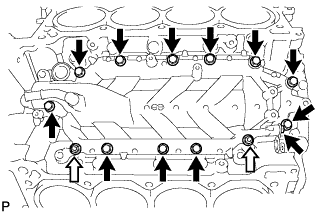
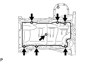
| 51. REMOVE NO. 1 OIL PAN SUB-ASSEMBLY |
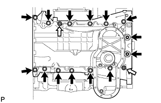
-
Remove the 14 bolts and 2 nuts.
Text in Illustration Bolt Nut HINT:
Be sure to clean the bolts and stud bolts, and check the threads for cracks or other damage.
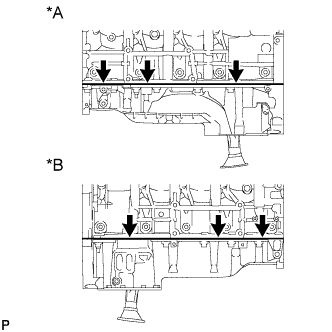
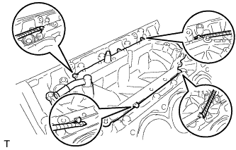
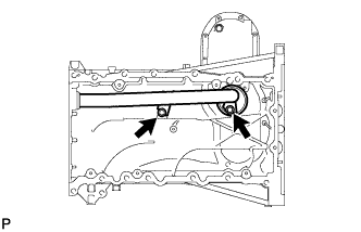
-
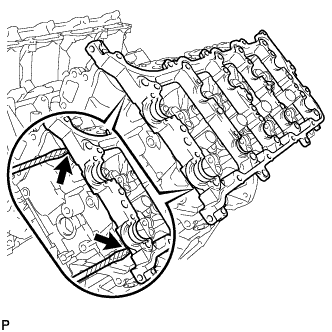
Remove the oil pan by prying between the oil pan and cylinder block with a screwdriver.
Text in Illustration *A LH Side *B RH Side NOTICE:
Be careful not to damage the contact surfaces of the cylinder block and oil pan.
HINT:
Tape the screwdriver tip before use.
| 52. REMOVE NO. 1 OIL PAN BAFFLE PLATE |
-
Remove the 7 bolts and baffle plate.
| 53. REMOVE OIL STRAINER SUB-ASSEMBLY |
-
Remove the 2 bolts, oil strainer and O-ring.
| 54. REMOVE ENGINE REAR OIL SEAL RETAINER |
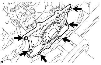
-
Remove the 6 bolts and oil seal retainer.
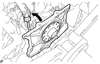
-
Using a screwdriver, pry out the oil seal retainer.
HINT:
Tape the screwdriver tip before use.
| 55. REMOVE OIL DRAIN PIPE SUB-ASSEMBLY |
-
Remove the bolt and oil drain pipe.
-
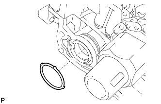
Remove the O-ring.
| 56. REMOVE REAR CRANKSHAFT OIL SEAL |
-
Place the oil seal retainer on wooden blocks.
Text in Illustration *1 Wooden Block
-
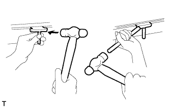
Using a screwdriver and hammer, tap out the oil seal.
| 57. REMOVE RING PIN |
NOTICE:
It is not necessary to remove the ring pin unless it is being replaced.
| 58. REMOVE STUD BOLT |
NOTICE:
If the stud bolt is deformed or its threads are damaged, replace it.