| 1. INSTALL FAN & GENERATOR V BELT |
-
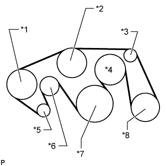
Set the V belt onto every part.
-
While turning the belt tensioner counterclockwise, remove the bar.
Text in Illustration *1 Vane Pump *2 Water Pump *3 No. 1 Idler *4 Fan *5 Generator *6 Belt Tensioner *7 Crankshaft *8 Cooler Compressor NOTICE:
Make sure that the V belt is properly set to each pulley.
-
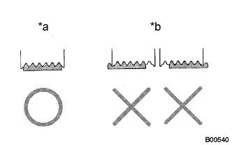
After installing the belt, check that it fits properly in the ribbed grooves.
Text in Illustration *a CORRECT *b INCORRECT HINT:
Make sure to check by hand that the belt has not slipped out of the grooves on the bottom of the pulley.
| 2. INSTALL V-BANK COVER SUB-ASSEMBLY |
-
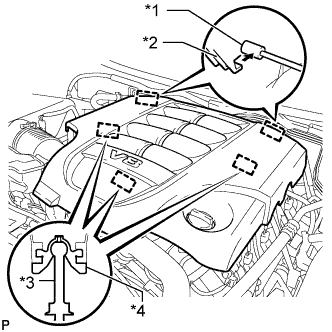
Attach the 2 V-bank cover hooks to the bracket. Then align the 3 V-bank cover grommets with the 3 pins, and press down on the V-bank cover to attach the pins.
Text in Illustration *1 Bracket *2 Hook *3 Pin *4 Grommet
| 3. INSTALL NO. 1 ENGINE UNDER COVER SUB-ASSEMBLY |
-
Install the No. 1 engine under cover with the 10 bolts.
Torque:
29 N*m{ 296 kgf*cm , 21 ft.*lbf }
| 4. INSTALL FRONT FENDER SPLASH SHIELD SUB-ASSEMBLY LH |
-
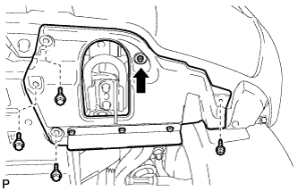
Push in the clip indicated by the arrow in the illustration to install the fender splash shield.
-
Install the 3 bolts and screw.
| 5. INSTALL FRONT FENDER SPLASH SHIELD SUB-ASSEMBLY RH |
HINT:
Use the same procedures described for the LH side.