| 1. INSPECT CYLINDER HEAD SET BOLT |
-
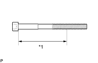
Using a vernier caliper, measure the diameter of the elongated thread at the measuring point.
Measuring point:
94 mm (3.70 in.) for intake side bolt
89 mm (3.50 in.) for exhaust side bolt
Standard diameter:
10.85 to 11.00 mm (0.427 to 0.433 in.)
Minimum diameter:
10.6 mm (0.417 in.)
Text in Illustration *1 Measuring Point If the diameter is less than the minimum, replace the cylinder head bolt.
HINT:
If a visual check reveals no excessively thin areas, check the center of the bolt (see illustration) and find the area that has the smallest diameter.
| 2. INSPECT CYLINDER HEAD SUB-ASSEMBLY |
-
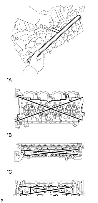
Using a precision straightedge and feeler gauge, measure the warpage of the surfaces where the cylinder head contacts the cylinder block and manifold.
Standard Warpage:
Item Specified Condition Cylinder head lower side 0.05 mm (0.00197 in.) Intake side 0.08 mm (0.00315 in.) Exhaust side 0.05 mm (0.00197 in.) Maximum warpage:
0.10 mm (0.00394 in.)
Text in Illustration *A Cylinder Head Lower Side *B Intake Side *C Exhaust Side If the warpage is more than the maximum, replace the cylinder head.
-
Using a dye penetrant, check the intake ports, exhaust ports and cylinder surface for cracks.
If cracked, replace the cylinder head.
| 3. INSTALL CYLINDER HEAD SUB-ASSEMBLY RH |
-
Clean the cylinder block with solvent.
-
Set the piston of the No. 1 cylinder to slightly ATDC.
-
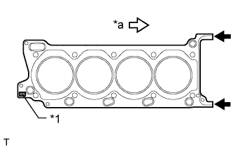
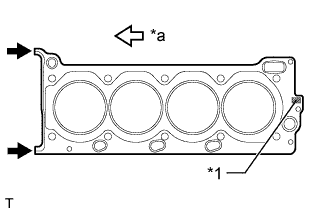
Place the cylinder head gasket on the cylinder block surface with the front face of the Lot No. stamp upward.
Text in Illustration *1 Lot No. *a Front NOTICE:
- Be careful of the installation direction.
- Make sure that no oil is on the front end (indicated by the arrows) of the cylinder head gasket.
-
Place the cylinder head on the cylinder block.
NOTICE:
- Ensure that no oil is on the mounting surface of the cylinder head.
- Gently place the cylinder head in order not to damage the gasket with the bottom part of the head.
HINT:
The cylinder head bolts are tightened in 3 progressive steps.
-
Apply a light coat of engine oil to the threads and under the heads of the cylinder head bolts.

-
Step 1:
-
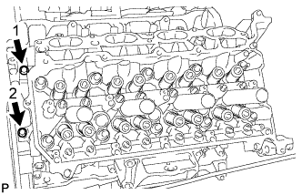
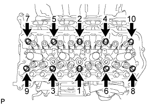
Using a 10 mm bi-hexagon wrench, install and uniformly tighten the 10 cylinder head bolts with the plate washers in several steps in the sequence shown in the illustration.
Torque:
36 N*m{ 367 kgf*cm , 27 ft.*lbf }
-
-
Step 2:
-
Mark the front side of each cylinder head bolt head with paint.
-
Tighten the cylinder head bolts another 90°.
-
-
Step 3:
-
Tighten the cylinder head bolts an additional 90°.
-
Check that the paint marks are now at a 180° angle to the front.
-
-
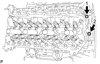
Install and uniformly tighten the 2 bolts in the sequence shown in the illustration.
Torque:
21 N*m{ 214 kgf*cm , 15 ft.*lbf }
| 4. INSTALL CYLINDER HEAD SUB-ASSEMBLY LH |
-
Clean the cylinder block with solvent.
-
Set the piston of the No. 1 cylinder to slightly ATDC.
-
Place the cylinder head gasket on the cylinder block surface with the front face of the Lot No. stamp upward.
Text in Illustration *1 Lot No. *a Front NOTICE:
- Be careful of the installation direction.
- Make sure that no oil is on the front end (indicated by the arrows) of the cylinder head gasket.
-
Place the cylinder head on the cylinder block.
NOTICE:
- Ensure that no oil is on the mounting surface of the cylinder head.
- Gently place the cylinder head in order not to damage the gasket with the bottom part of the head.
HINT:
The cylinder head bolts are tightened in 3 progressive steps.
-
Apply a light coat of engine oil to the threads and under the heads of the cylinder head bolts.
-
Step 1:
HINT:
The cylinder head bolts are tightened in 3 progressive steps.
-
Using a 10 mm bi-hexagon wrench, install and uniformly tighten the 10 cylinder head bolts with the plate washers in several steps in the sequence shown in the illustration.
Torque:
36 N*m{ 367 kgf*cm , 27 ft.*lbf }
-
-
Step 2:
-
Mark the front side of each cylinder head bolt head with paint.
-
Tighten the cylinder head bolts another 90°.
-
-
Step 3:
-
Tighten the cylinder head bolts an additional 90°.
-
Check that the paint marks are now at a 180° angle to the front.
-
-
Install and uniformly tighten the 2 bolts in the sequence shown in the illustration.
Torque:
21 N*m{ 214 kgf*cm , 15 ft.*lbf }
| 5. INSTALL VALVE STEM CAP |
-
Apply a light coat of engine oil to the valve stem caps.
-
Install the 32 valve stem caps to the cylinder heads.
| 6. INSTALL VALVE LASH ADJUSTER ASSEMBLY |
-
Inspect the valve lash adjuster before installing it.
-
Install the 32 valve lash adjusters to the cylinder heads.
NOTICE:
Install the lash adjuster to the same place it was removed from.
| 7. INSTALL NO. 1 VALVE ROCKER ARM SUB-ASSEMBLY |
-
Apply engine oil to the lash adjuster tips and valve stem cap ends.
-
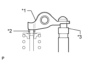
Install the 32 valve rocker arms as shown in the illustration.
Text in Illustration *1 Valve Rocker Arm *2 Valve Stem Cap *3 Valve Lash Adjuster
| 8. INSTALL CAMSHAFT |
| 9. INSTALL EXHAUST MANIFOLD SUB-ASSEMBLY |