| 1. INSPECT NO. 1 OIL NOZZLE SUB-ASSEMBLY |
-
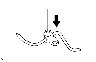
Push the check valve with a pin to check if it is stuck.
If stuck, replace the No. 1 oil nozzle sub-assembly.
-
Push the check valve with a pin to check if it moves smoothly.
If it does not move smoothly, clean or replace the No. 1 oil nozzle sub-assembly.
-
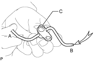
While covering A, apply air into B. Check that air does not leak through C. Perform the check again while covering B and applying air into A.
If air leaks, clean or replace the No. 1 oil nozzle sub-assembly.
-
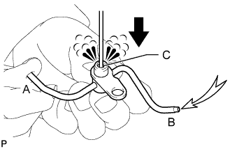
Push the check valve while covering A, and apply air into B. Check that air passes through C. Perform the check again while covering B, pushing the check valve and applying air into A.
If air does not pass through C, clean or replace the No. 1 oil nozzle sub-assembly.
| 2. CHECK CYLINDER BLOCK SUB-ASSEMBLY |
-
Visually check the cylinder for vertical scratches.
If necessary, replace the cylinder block.
| 3. INSPECT CYLINDER BLOCK FOR WARPAGE |
-
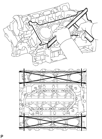
Using a precision straightedge and feeler gauge, measure the warpage of the surfaces where the cylinder head gaskets contact the cylinder block.
Maximum warpage:
0.07 mm (0.00276 in.)
If the warpage is more than the maximum, replace the cylinder block.
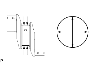
| 4. INSPECT CYLINDER BORE |
-
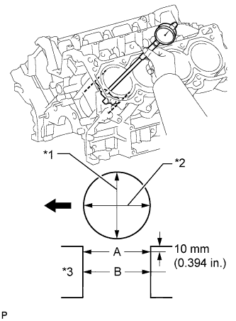
Using a cylinder gauge, measure the cylinder bore diameter at positions A and B in the thrust and axial directions.
Standard diameter:
94.000 to 94.012 mm (3.7008 to 3.7013 in.)
Maximum diameter:
94.200 mm (3.7087 in.)
Text in Illustration *1 Thrust Direction *2 Axial Direction *3 Center 
Front If the diameter is more than the maximum, replace the cylinder block.
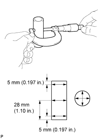
| 5. INSPECT PISTON SUB-ASSEMBLY WITH PIN |
-
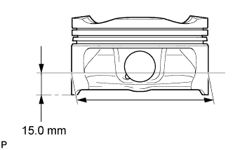
Using a micrometer, measure the piston diameter at a position that is 15.0 mm (0.591 in.) from the bottom of the piston (refer to the illustration).
Standard diameter:
93.950 to 93.960 mm (3.6988 to 3.6992 in.)
Minimum diameter:
93.815 mm (3.6935 in.)
If the diameter is less than the minimum, replace the piston.
| 6. INSPECT PISTON OIL CLEARANCE |
-
Measure the cylinder bore diameter in the thrust direction.
-
Subtract the piston diameter measurement from the cylinder bore diameter measurement.
Standard oil clearance:
0.020 to 0.072 mm (0.000787 to 0.00283 in.)
Maximum oil clearance:
0.385 mm (0.0152 in.)
If the oil clearance is more than the maximum, replace all the pistons. If necessary, replace the cylinder block.
| 7. INSPECT RING GROOVE CLEARANCE |
-
Using a feeler gauge, measure the clearance between a new piston ring and the wall of the ring groove.
Standard Ring Groove Clearance:
Item Specified Condition No. 1 ring 0.020 to 0.070 mm (0.000787 to 0.00276 in.) No. 2 ring 0.020 to 0.060 mm (0.000787 to 0.00236 in.) Oil ring expander 0.070 to 0.145 mm (0.00276 to 0.00571 in.) If the clearance is not as specified, replace the piston.
| 8. INSPECT PISTON RING END GAP |
-
Insert the piston ring into the cylinder bore.
-
Using a piston, push the piston ring a little beyond the bottom of the ring travel, 60 mm (2.36 in.) from the top of the cylinder block.
-
Using a feeler gauge, measure the end gap.
Standard End Gap:
Item Specified Condition No. 1 ring 0.23 to 0.33 mm (0.00906 to 0.0130 in.) No. 2 ring 0.40 to 0.50 mm (0.0157 to 0.0197 in.) Oil ring expander 0.10 to 0.40 mm (0.00394 to 0.0157 in.) Maximum End Gap:
Item Specified Condition No. 1 ring 0.42 mm (0.0165 in.) No. 2 ring 0.55 mm (0.0217 in.) Oil ring expander 0.45 mm (0.0177 in.) If the end gap is more than the maximum, replace the piston ring. If the end gap is more than the maximum even with a new piston ring, replace the cylinder block.
| 9. INSPECT PISTON PIN OIL CLEARANCE |
-
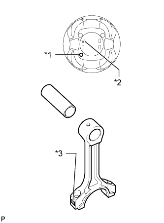
Check each mark on the piston, piston pin and connecting rod.
Text in Illustration *1 Front Mark *2 Position Pin Hole Inside Diameter Mark *3 Connecting Rod Bush Inside Diameter Mark
-
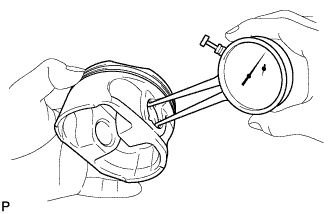
Using a caliper gauge, measure the inside diameter of the piston pin hole.
Standard Piston Pin Hole Inside Diameter:
Mark Specified Condition A 21.998 to 22.001 mm (0.86606 to 0.86618 in.) B 22.001 to 22.004 mm (0.86618 to 0.86630 in.) C 22.004 to 22.007 mm (0.86630 to 0.86642 in.)
-
Using a micrometer, measure the piston pin diameter.
Standard Piston Pin Diameter:
Mark Specified Condition A 21.997 to 22.000 mm (0.86602 to 0.86614 in.) B 22.000 to 22.003 mm (0.86614 to 0.86626 in.) C 22.003 to 22.006 mm (0.86626 to 0.86638 in.)
-
Subtract the piston pin diameter measurement from the piston pin hole diameter measurement.
Standard oil clearance:
-0.002 to 0.004 mm (-0.0000787 to 0.000157 in.)
Maximum oil clearance:
0.015 mm (0.000591 in.)
If the oil clearance is more than the maximum, replace the piston and piston pin as a set.
-
Using a caliper gauge, measure the inside diameter of the connecting rod bush.
Standard Bush Inside Diameter:
Mark Specified Condition A 22.005 to 22.008 mm (0.86634 to 0.86645 in.) B 22.008 to 22.011 mm (0.86645 to 0.86657 in.) C 22.011 to 22.014 mm (0.86657 to 0.86669 in.)
-
Subtract the piston pin diameter measurement from the bush inside diameter measurement.
Standard oil clearance:
0.005 to 0.011 mm (0.000197 to 0.000433 in.)
Maximum oil clearance:
0.03 mm (0.00118 in.)
If the oil clearance is more than the maximum, replace the connecting rod, and replace the piston and pin as a set.
| 10. INSPECT CONNECTING ROD SUB-ASSEMBLY |
-
Using a rod aligner and feeler gauge, check the connecting rod alignment.
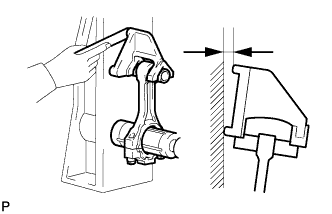
-
Check for bend.
Maximum bend:
0.05 mm (0.00197 in.) per 100 mm (3.94 in.)
If the bend is more than the maximum, replace the connecting rod.
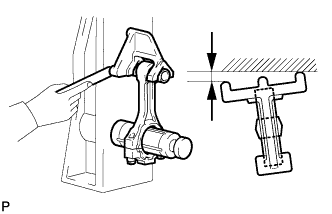
-
Check for twist.
Maximum twist:
0.15 mm (0.00591 in.) per 100 mm (3.94 in.)
If the twist is more than the maximum, replace the connecting rod.
-
| 11. INSPECT CONNECTING ROD BOLT |
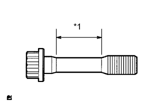
-
Using a vernier caliper, measure the tension portion diameter of the bolt.
Standard diameter:
8.5 to 8.6 mm (0.335 to 0.339 in.)
Minimum diameter:
8.3 mm (0.327 in.)
Text in Illustration *1 Measuring Point If the diameter is less than the minimum, replace the bolt.
| 12. INSPECT CRANKSHAFT |
-
Inspect circle runout.
-
Place the crankshaft on V-blocks.
-
Using a dial indicator, measure the circle runout at the center journal.
Maximum circle runout:
0.06 mm (0.00236 in.)
If the circle runout is more than the maximum, replace the crankshaft.
-
-
Inspect the main journals.
-
Using a micrometer, measure the diameter of each main journal.
Standard journal diameter:
66.988 to 67.000 mm (2.6373 to 2.6378 in.)
If the diameter is not as specified, check the oil clearance. If necessary, replace the crankshaft.
-
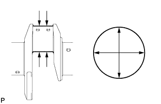
Check each main journal for taper and out-of-round as shown in the illustration.
Maximum taper and out-of-round:
0.02 mm (0.000787 in.)
If the taper and out-of-round is more than the maximum, replace the crankshaft.
-
-
Inspect the crank pins.
-
Using a micrometer, measure the diameter of each crank pin.
Standard crank pin diameter:
55.982 to 56.000 mm (2.2040 to 2.2047 in.)
If the diameter is not as specified, check the oil clearance. If necessary, replace the crankshaft.
-
Check each crank pin for taper and out-of-round as shown in the illustration.
Maximum taper and out-of-round:
0.02 mm (0.000787 in.)
If the taper and out-of-round is more than the maximum, replace the crankshaft.
-
| 13. INSPECT CRANKSHAFT OIL CLEARANCE |
-
Clean each main journal and bearing.
-
Check each main journal and bearing for pitting and scratches.
If the journal or bearing is damaged, replace the bearing.
-
Place the crankshaft on the cylinder block.
-
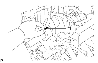
Lay a strip of Plastigage across each journal.
Text in Illustration *1 Plastigage
-
Install the crankshaft bearing caps.
-
Remove the 30 bolts and bearing caps.
-
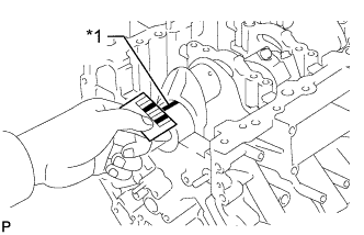
Measure the Plastigage at its widest point.
Standard Oil Clearance:
Number Mark Specified Condition No. 1 and No. 5 journals 0.017 to 0.030 mm (0.000669 to 0.00118 in.) Other journals 0.024 to 0.037 mm (0.000945 to 0.00146 in.) Maximum Oil Clearance:
Number Mark Specified Condition No. 1 and No. 5 journals 0.050 mm (0.00197 in.) Other journals 0.060 mm (0.00236 in.) Text in Illustration *1 Plastigage If the oil clearance is more than the maximum, replace the bearings. If necessary, replace the crankshaft.
HINT:
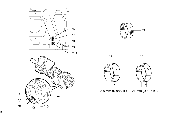
If replacing a bearing, replace it with one that has the same number. If the number of the bearing cannot be determined, select the correct bearing by adding together the numbers imprinted on the cylinder block and crankshaft. Refer to the table below for the appropriate bearing number. There are 6 sizes of standard bearings. For the No. 1 and No. 5 position bearings, use bearings marked 4, 5, 6, 7, 8 or 9. For other bearings, use bearings marked 3, 4, 5, 6, 7 or 8.
Text in Illustration *1 Cylinder Block Number Mark *2 Crankshaft Number Mark *3 Number Mark *4 No. 1 and No. 5 Journal Bearings *5 No. 2, No. 3 and No. 4 Journal Bearings *6 No. 1 *7 No. 2 *8 No. 3 *9 No. 4 *10 No. 5 Example:
Cylinder block "07" + Crankshaft "06" = Total number 13 (Use upper bearing "6" and lower bearing "7")
HINT:
A = Cylinder block number mark
B = Crankshaft number mark
Standard Bearing Center Wall Thickness:
No. 1 and No. 5 Journals (A) + (B) Upper Bearing Lower Bearing Number Mark Specified Condition Number Mark Specified Condition 00 to 02 4 2.501 to 2.504 (0.0985 to 0.0986 in.) 5 2.488 to 2.491 (0.0980 to 0.0981 in.) 03 to 05 5 2.504 to 2.507 (0.0986 to 0.0987 in.) 5 2.488 to 2.491 (0.0980 to 0.0981 in.) 06 to 08 5 2.504 to 2.507 (0.0986 to 0.0987 in.) 6 2.491 to 2.494 (0.0981 to 0.0982 in.) 09 to 11 6 2.507 to 2.510 (0.0987 to 0.0988 in.) 6 2.491 to 2.494 (0.0981 to 0.0982 in.) 12 to 14 6 2.507 to 2.510 (0.0987 to 0.0988 in.) 7 2.494 to 2.497 (0.0982 to 0.0983 in.) 15 to 17 7 2.510 to 2.513 (0.0988 to 0.0989 in.) 7 2.494 to 2.497 (0.0982 to 0.0983 in.) 18 to 20 7 2.510 to 2.513 (0.0988 to 0.0989 in.) 8 2.497 to 2.500 (0.0983 to 0.0984 in.) 21 to 23 8 2.513 to 2.516 (0.0989 to 0.0991 in.) 8 2.497 to 2.500 (0.0983 to 0.0984 in.) 24 to 26 8 2.513 to 2.516 (0.0989 to 0.0991 in.) 9 2.500 to 2.503 (0.0984 to 0.0985 in.) 27 to 28 9 2.516 to 2.519 (0.0991 to 0.0992 in.) 9 2.500 to 2.503 (0.0984 to 0.0985 in.) Other Journals:
(A) + (B) Upper Bearing Lower Bearing Number Mark Specified Condition Number Mark Specified Condition 00 to 02 3 2.482 to 2.485 (0.0977 to 0.0978 in.) 4 2.501 to 2.504 (0.0985 to 0.0986 in.) 03 to 05 4 2.485 to 2.488 (0.0978 to 0.0980 in.) 4 2.501 to 2.504 (0.0985 to 0.0986 in.) 06 to 08 4 2.485 to 2.488 (0.0978 to 0.0980 in.) 5 2.504 to 2.507 (0.0986 to 0.0987 in.) 09 to 11 5 2.488 to 2.491 (0.0980 to 0.0981 in.) 5 2.504 to 2.507 (0.0986 to 0.0987 in.) 12 to 14 5 2.488 to 2.491 (0.0980 to 0.0981 in.) 6 2.507 to 2.510 (0.0987 to 0.0988 in.) 15 to 17 6 2.491 to 2.494 (0.0981 to 0.0982 in.) 6 2.507 to 2.510 (0.0987 to 0.0988 in.) 18 to 20 6 2.491 to 2.494 (0.0981 to 0.0982 in.) 7 2.510 to 2.513 (0.0988 to 0.0989 in.) 21 to 23 7 2.494 to 2.497 (0.0982 to 0.0983 in.) 7 2.510 to 2.513 (0.0988 to 0.0989 in.) 24 to 26 7 2.494 to 2.497 (0.0982 to 0.0983 in.) 8 2.513 to 2.516 (0.0989 to 0.0991 in.) 27 to 28 8 2.497 to 2.500 (0.0983 to 0.0984 in.) 8 2.513 to 2.516 (0.0989 to 0.0991 in.)
-
Completely remove the Plastigage.
| 14. INSPECT CRANKSHAFT BEARING CAP SET BOLT |
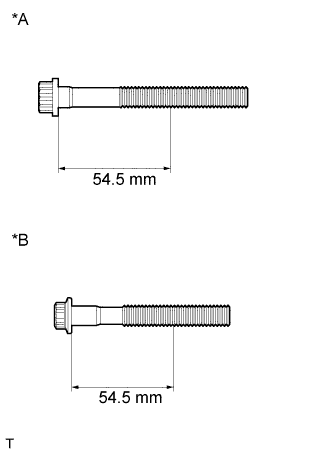
-
Using a vernier caliper, measure the minimum diameter of the elongated thread at the measuring point.
Measuring point:
54.5 mm (2.15 in.)
Standard Diameter:
Item Specified Condition Bolt A 10.5 to 11.0 mm (0.413 to 0.433 in.) Bolt B 9.5 to 10.0 mm (0.374 to 0.394 in.) Minimum Diameter:
Item Specified Condition Bolt A 10.4 mm (0.409 in.) Bolt B 9.4 mm (0.370 in.) Text in Illustration *A Bolt A *B Bolt B If the diameter is less than the minimum, replace the bolt.