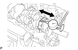
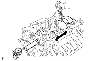
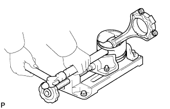
| 1. INSPECT CONNECTING ROD THRUST CLEARANCE |
-
Using a dial indicator, measure the thrust clearance while moving the connecting rod back and forth.
Standard thrust clearance:
0.15 to 0.55 mm (0.00591 to 0.0217 in.)
Maximum thrust clearance:
0.70 mm (0.0276 in.)
If the thrust clearance is more than the maximum, replace one or more connecting rods as necessary.
If necessary, replace the crankshaft.
| 2. INSPECT CONNECTING ROD OIL CLEARANCE |
-
Check that the front mark on the connecting rod and cap are aligned to ensure correct reassembly.
-
Remove the 2 connecting rod cap bolts.
-
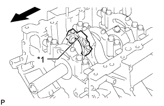
Using the 2 removed connecting rod cap bolts, remove the connecting rod cap and lower bearing by wiggling the connecting rod cap right and left.
HINT:
Keep the lower bearing inserted to the connecting rod cap.
-
Check the crank pin and bearing for pitting and scratches.
If the crank pin or bearing is damaged, replace the bearings. If necessary, replace the crankshaft.
-
Clean the crank pin and bearing.
-
Lay a strip of Plastigage on the crank pin.
Text in Illustration *1 Plastigage
-
Place the connecting rod cap on the connecting rod with the front mark facing forward.
Text in Illustration *1 Front Mark 
Front
-
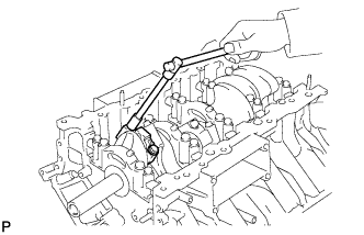
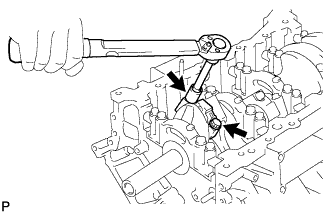
Install and alternately tighten the bolts of the connecting rod cap in several steps.
Torque:
40 N*m{ 408 kgf*cm , 30 ft.*lbf }
NOTICE:
Do not turn the crankshaft.
-
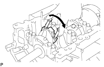
Mark the front side of each connecting rod cap bolt with paint.
-
Tighten the cap bolts 90° as shown in the illustration.
-
Check that the painted marks are now at a 90° angle to the front.
NOTICE:
Do not turn the crankshaft.
-
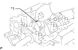
Remove the 2 connecting rod cap bolts.
-
Using the 2 removed connecting rod cap bolts, remove the connecting rod cap and lower bearing by wiggling the connecting rod cap right and left.
HINT:
Keep the lower bearing inserted to the connecting rod cap.
-
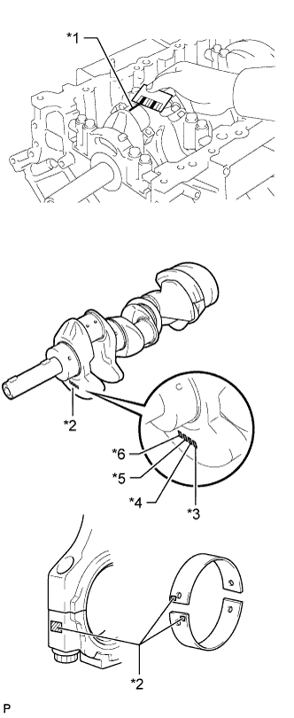
Measure the Plastigage at its widest point.
Standard oil clearance:
0.025 to 0.050 mm (0.000984 to 0.00197 in.)
Maximum oil clearance:
0.070 mm (0.00276 in.)
Text in Illustration *1 Plastigage *2 Number Mark *3 No. 1 *4 No. 2 *5 No. 3 *6 No. 4 If the oil clearance is more than the maximum, replace the bearings. If necessary, replace the crankshaft.
HINT:
- If replacing a bearing, replace it with one that has the same number as its respective connecting rod cap. The standard thickness of each bearing is indicated by a 1, 2, 3 or 4 mark on its surface.
- Select the correct bearing by adding together the number marks imprinted on the connecting rod big end and crank pin.
Example:
Connecting rod "1" + Crank pin "2" = 3 (Use bearing "3")
Reference:
Standard Sized Bearing Center Wall Thickness:
Mark Thickness 2 1.489 to 1.492 mm (0.0586 to 0.0587 in.) 3 1.492 to 1.495 mm (0.0587 to 0.0589 in.) 4 1.495 to 1.498 mm (0.0589 to 0.0590 in.) 5 1.498 to 1.501 mm (0.0590 to 0.0591 in.) 6 1.501 to 1.504 mm (0.0591 to 0.0592 in.) 7 1.504 to 1.507 mm (0.0592 to 0.0593 in.) Connecting Rod Big End Inside Diameter:
Mark Thickness 1 59.000 to 59.006 mm (2.32283 to 2.32307 in.) 2 59.006 to 59.012 mm (2.32307 to 2.32330 in.) 3 59.012 to 59.018 mm (2.32330 to 2.32354 in.) 4 59.018 to 59.024 mm (2.32354 to 2.32377 in.) Crankshaft Pin Diameter:
Mark Thickness 1 55.994 to 56.000 mm (2.20448 to 2.20472 in.) 2 55.988 to 55.994 mm (2.20425 to 2.20448 in.) 3 55.982 to 55.988 mm (2.20401 to 2.20425 in.)
-
Completely remove the Plastigage.
-
Perform the inspection above for each cylinder.
| 3. REMOVE PISTON AND CONNECTING ROD |
-
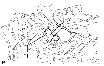
Using a ridge reamer, remove all the carbon from the top of the cylinder.
Text in Illustration *1 Ridge Reamer
-
Remove the 16 cap bolts, 8 connecting rod caps and 8 lower bearings.
-
Push the 8 pistons and 8 connecting rods through the top of the cylinder block.
HINT:
- Keep the bearing, connecting rod and cap together.
- Arrange the piston and connecting rods in the correct order.
| 4. REMOVE CONNECTING ROD BEARING |
-
Remove the connecting rod bearings from the connecting rods and connecting rod caps.
HINT:
Arrange the removed parts in the correct order.
| 5. INSPECT CRANKSHAFT THRUST CLEARANCE |
-
Using a dial indicator, measure the thrust clearance while prying the crankshaft back and forth with a screwdriver.
Standard thrust clearance:
0.020 to 0.220 mm (0.000787 to 0.00866 in.)
Maximum thrust clearance:
0.30 mm (0.0118 in.)
If the thrust clearance is more than the maximum, replace the thrust washers as a set. If necessary, replace the crankshaft.
Standard thrust washer thickness:
2.44 to 2.49 mm (0.0961 to 0.0980 in.)
| 6. REMOVE CRANKSHAFT |
-
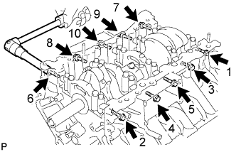
Uniformly loosen and remove the 10 bearing cap bolts and 10 seal washers in several steps in the sequence shown in the illustration.
-
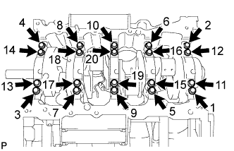
Uniformly loosen and remove the 20 bearing cap bolts in several steps in the sequence shown in the illustration.
-
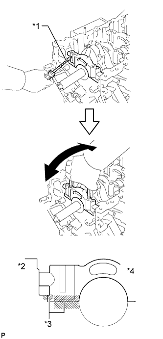
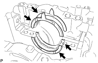
Using a screwdriver, slightly pry up the 5 main bearing caps.
Text in Illustration *1 Protective Tape *2 Cylinder Block *3 Joint Surface *4 Bearing Cap NOTICE:
- Be careful not to damage the joint surface of the cylinder block and main bearing caps.
- Pry up the left and right side of the cap little by little.
HINT:
Tape the screwdriver tip before use.
-
Using the 2 inside position crankshaft bearing cap bolts, loosen each crankshaft bearing cap by moving it forward and backward, and remove each crankshaft bearing cap.
-
Remove the crankshaft.
| 7. REMOVE CRANKSHAFT BEARING |
-
Remove the crankshaft bearings from the bearing caps and cylinder block.
HINT:
Arrange the removed parts in the correct order.
| 8. REMOVE CRANKSHAFT THRUST WASHER SET |
-
Remove the thrust washer set from the cylinder block and No. 3 bearing cap.
| 9. REMOVE NO. 1 OIL NOZZLE SUB-ASSEMBLY |
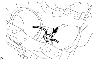
-
Using a 5 mm hexagon wrench, remove the 4 bolts and 4 oil nozzles.
| 10. REMOVE PISTON RING SET |
HINT:
Arrange the piston rings in the correct order.
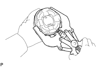
-
Using a piston ring expander, remove the 2 compression rings.
-
Remove the 2 side rails and oil ring expander by hand.
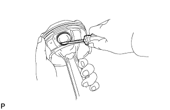
| 11. REMOVE PISTON WITH PIN SUB-ASSEMBLY |
-
Disconnect the connecting rod from the piston.
-
Using a small screwdriver, pry off the 2 snap rings from the piston.
-
Gradually heat the piston to approximately 80°C (176°F).
-
Using a brass bar and plastic-faced hammer, lightly tap out the piston pin. Then remove the connecting rod.
HINT:
- The piston and pin are a matched set.
- Arrange the pistons, pins, rings, connecting rods and bearings in the correct order.
-
-
Clean the piston.
-
Using a gasket scraper, remove the carbon from the piston top.
-
Using a groove cleaning tool or broken ring, clean the piston ring grooves.
-
Using solvent and a brush, thoroughly clean the piston.
NOTICE:
Do not use a wire brush.
-
| 12. REMOVE STUD BOLT |
NOTICE:
If the stud bolt is deformed or its threads are damaged, replace it.