| 1. DISCHARGE FUEL SYSTEM PRESSURE |
| 2. DISCONNECT CABLE FROM NEGATIVE BATTERY TERMINAL |
NOTICE:
When disconnecting the cable, some systems need to be initialized after the cable is reconnected .
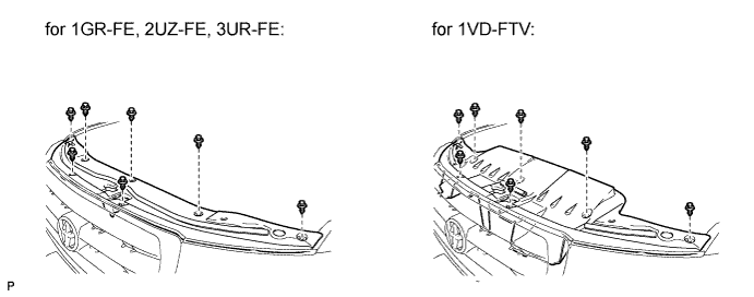
| 3. REMOVE UPPER RADIATOR SUPPORT SEAL |
-
Remove the 7 clips and radiator support seal.
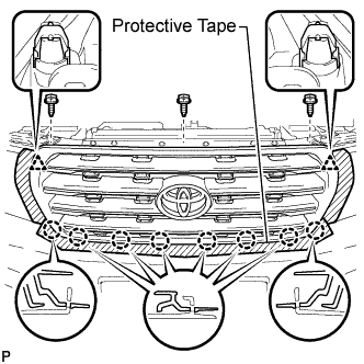
| 4. REMOVE RADIATOR GRILLE |
-
Put protective tape around the radiator grille.
-
Remove the 3 screws.
-
Detach the 2 clips and 8 claws, and remove the radiator grille.
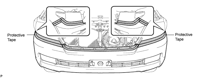
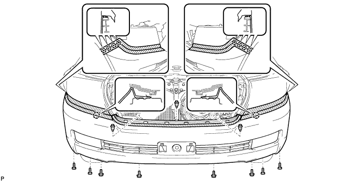
| 5. REMOVE FRONT BUMPER COVER |
HINT:
For the front bumper cover with garnish, use the procedures described below.
-
Put protective tape around the bumper cover.
-
Using a T30 "TORX" socket, remove the 6 screws.
-
Remove the 3 clips, 4 screws and 4 bolts.
-
w/o TOYOTA Parking Assist-sensor System, w/o Fog Light:
Detach the 10 claws and remove the bumper cover.
-
w/ TOYOTA Parking Assist-sensor System or w/ Fog Light:
Detach the 10 claws, disconnect the No. 4 engine room wire connector and remove the bumper cover.
-
w/ Headlight Cleaner System:
Disconnect the headlight cleaner hose and remove the bumper cover.
| 6. REMOVE TRANSMISSION OIL COOLER AIR DUCT |
-
Remove the 4 bolts and oil cooler air duct.
| 7. DISCONNECT RADIATOR SIDE DEFLECTOR LH |
-
Using a clip remover, remove the 4 clips and disconnect the side deflector.
| 8. REMOVE FRONT FENDER MAIN SEAL LH |
-
Using a clip remover, detach the 3 clips and remove the fender main seal.
| 9. REMOVE FRONT FENDER MAIN SEAL RH |
HINT:
Use the same procedures described for the LH side.
| 10. REMOVE FRONT WIPER ARM LH |
-
Remove the nut, wiper arm and blade.
| 11. REMOVE FRONT WIPER ARM RH |
-
Remove the nut, wiper arm and blade.
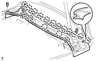
| 12. REMOVE HOOD TO COWL TOP SEAL |
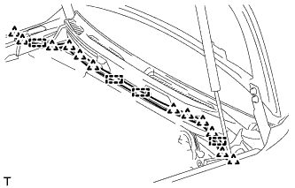
-
Using a clip remover, detach the 12 clips, 4 clamps and remove the hood to cowl top seal.
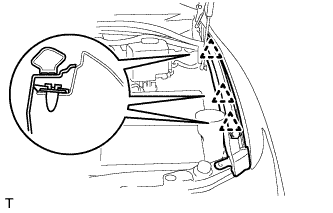
| 13. REMOVE COWL TOP VENTILATOR LOUVER SUB-ASSEMBLY |
-
Remove the washer hose.
-
Remove the 2 clips.
-
Detach the 17 claws and remove the cowl top ventilator louver sub-assembly.
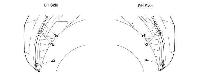
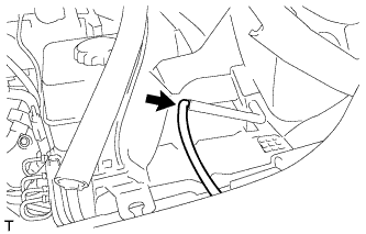
| 14. REMOVE FRONT FENDER SPLASH SHIELD SUB-ASSEMBLY LH |
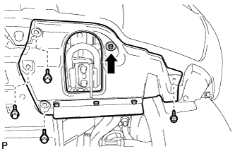
-
Remove the 3 bolts and screw.
-
Turn the clip indicated by the arrow in the illustration to remove the fender splash shield.
| 15. REMOVE FRONT FENDER SPLASH SHIELD SUB-ASSEMBLY RH |
HINT:
Use the same procedures described for the LH side.
| 16. REMOVE NO. 1 ENGINE UNDER COVER SUB-ASSEMBLY |
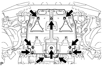
-
Remove the 10 bolts and No. 1 engine under cover.
| 17. REMOVE NO. 2 ENGINE UNDER COVER |
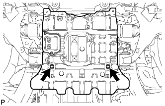
-
Remove the 2 bolts and No. 2 engine under cover.
| 18. REMOVE FRONT FENDER APRON SEAL LH |
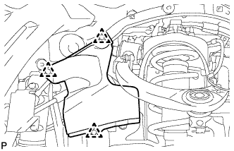
-
Using a clip remover, remove the 3 clips and fender apron seal.
| 19. REMOVE FRONT FENDER APRON SEAL FRONT RH |
-
Using a clip remover, remove the 3 clips and fender apron seal.
| 20. DRAIN ENGINE OIL |
-
Remove the oil filler cap.
-
Remove the 2 bolts and No. 2 engine under cover seal.
-
Remove the oil pan drain plug and gasket, and drain the engine oil into a container.
-
Install a new gasket and the oil pan drain plug.
Torque:
40 N*m{ 408 kgf*cm , 30 ft.*lbf }
| 21. DRAIN ENGINE COOLANT |
CAUTION:
Do not remove the radiator cap while the engine and radiator are still hot. Pressurized, hot engine coolant and steam may be released and cause serious burns.
-
Loosen the radiator drain cock plug.
HINT:
Collect the coolant in a container and dispose of it according to the regulations in your area.
-
Remove the radiator cap. Then drain the coolant from the radiator.
-
Loosen the 2 cylinder block drain cock plugs. Then drain the coolant from the engine.
-
Tighten the 2 cylinder block drain cock plugs.
Torque:
13 N*m{ 133 kgf*cm , 10 ft.*lbf }
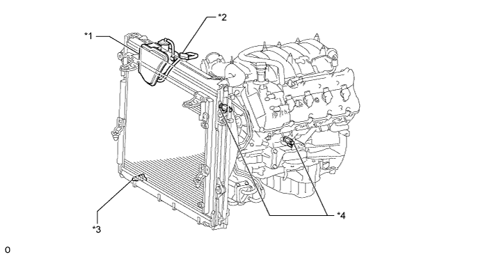
Text in Illustration *1 Radiator Reservoir *2 Radiator Cap *3 Radiator Drain Cock Plug *4 Cylinder Block Drain Cock Plug
-
Tighten the radiator drain cock plug by hand.
| 22. REMOVE V-BANK COVER SUB-ASSEMBLY |
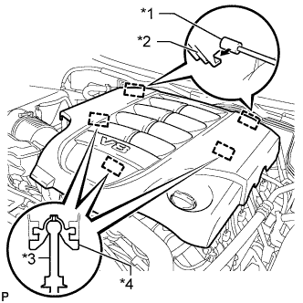
-
Raise the front of the V-bank cover to detach the 3 pins. Then remove the 2 V-bank cover hooks from the bracket, and remove the V-bank cover.
Text in Illustration *1 Bracket *2 Hook *3 Pin *4 Grommet
| 23. REMOVE AIR CLEANER HOSE ASSEMBLY |
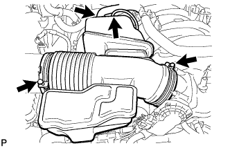
-
Disconnect the vacuum hose and No. 2 ventilation hose.
-
Loosen the 2 hose clamps.
-
Remove the air cleaner hose.
| 24. REMOVE AIR CLEANER ASSEMBLY |
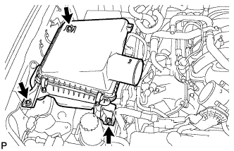
-
Remove the 3 bolts and air cleaner.
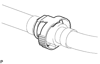
| 25. REMOVE NO. 1 RADIATOR HOSE |
| 26. REMOVE NO. 2 RADIATOR HOSE |
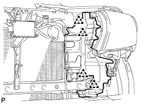
| 27. REMOVE FAN SHROUD |
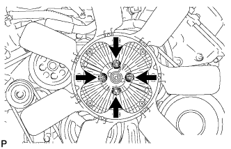
-
Loosen the 4 nuts holding the fluid coupling fan.
-
Remove the fan and generator V-belt.
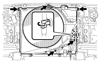
-
Disconnect the reservoir hose from the upper radiator tank.
-
Detach the claw to open the flexible hose clamp.
-
Remove the 2 bolts and disconnect the oil cooler tube from the fan shroud.
-
Remove the 2 bolts holding the fan shroud.
-
Remove the 4 nuts of the fluid coupling fan, and then remove the shroud together with the coupling fan.
NOTICE:
Be careful not to damage the radiator core.
-
Remove the fan pulley.
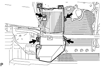
| 28. REMOVE RADIATOR ASSEMBLY |
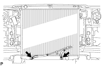
-
Disconnect the 2 oil cooler hoses.
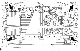
-
Remove the 4 bolts and radiator.
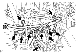
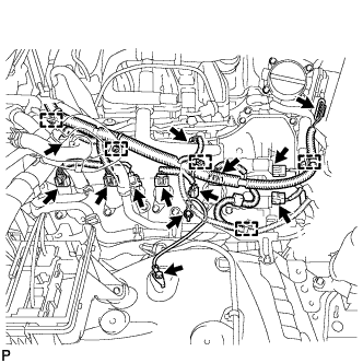
| 29. DISCONNECT ENGINE WIRE |
-
Engine Room LH Side:
-
Remove the engine room relay block cover.
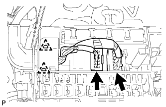
-
Disconnect the 2 connectors and 2 clips from the engine room junction block.
-
Disconnect the injector connector.
-
Disconnect the 4 ignition coil connectors.
-
Disconnect the 2 VVT sensor connectors.
-
Disconnect the 4 clamps.
-
Remove the 2 bolts and ground wire.
-
Disconnect the noise filter connector.
-
Disconnect the engine coolant temperature sensor connector.
-
Disconnect the 2 camshaft timing oil control valve connectors.
-
Disconnect the camshaft position sensor connector.
-
Disconnect the 3 clamps.
-
Disconnect the cooler compressor connector.
-
-
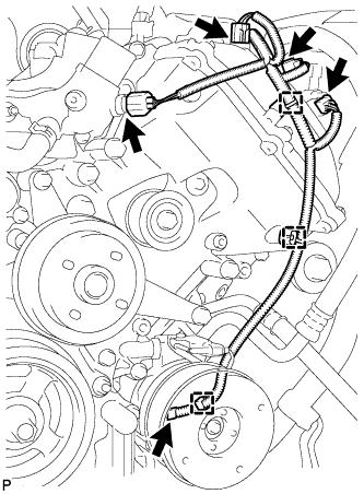
Engine Room RH Side:
-
Disconnect the 2 camshaft timing oil control valve connectors.
-
Disconnect the 4 ignition coil connectors.
-
Disconnect the injector connector.
-
Disconnect the 2 VVT sensor connectors.
-
Disconnect the noise filter connector.
-
Remove the 2 bolts and ground wire.
-
Disconnect the throttle position sensor and throttle control motor connector.
-
Disconnect the 5 clamps.
-
-
Disconnect the 2 clamps and power steering oil pressure switch connector.
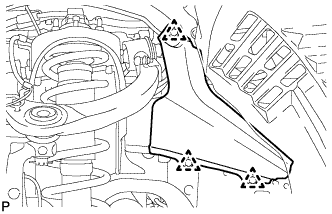
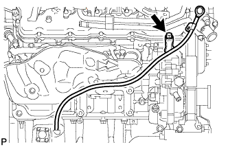
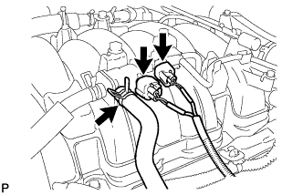
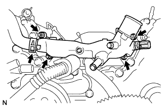
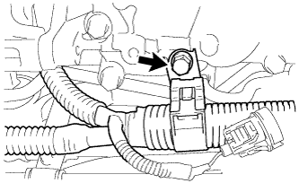
| 30. DISCONNECT WATER PIPE AND HOSE SUB-ASSEMBLY |
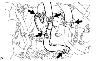
-
Disconnect the 3 hoses.
-
Remove the 2 bolts and disconnect the water pipe and hose from the cylinder head cover.
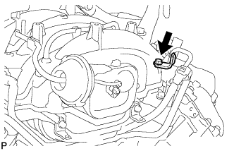
| 31. DISCONNECT COOLER COMPRESSOR ASSEMBLY |
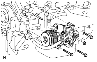
-
Remove the 3 bolts, nut and stud bolt, and disconnect the cooler compressor.
HINT:
It is not necessary to completely remove the compressor. With the hoses connected to the compressor, hang the compressor on the vehicle body with a rope.
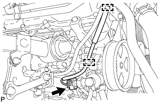
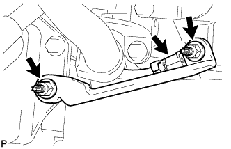
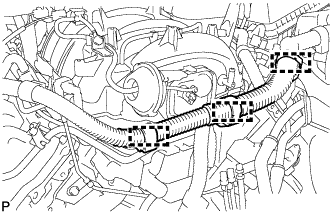
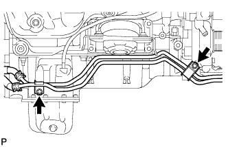
| 32. DISCONNECT NO. 2 FUEL TUBE SUB-ASSEMBLY |
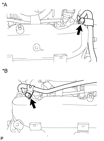
-
Remove the 2 bolts and disconnect the fuel tube.
Text in Illustration *A LH Side *B RH Side
| 33. REMOVE OIL FILTER ELEMENT |
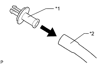
-
Connect a hose with an inside diameter of 15 mm (0.591 in.) to the pipe.
Text in Illustration *1 Pipe *2 Hose
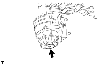
-
Remove the oil filter drain plug.
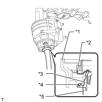
-
Install the pipe to the oil filter cap.
Text in Illustration *1 Cap *2 Valve *3 Pipe *4 O-Ring *5 Hose NOTICE:
If the O-ring is removed with the drain plug, install the O-ring together with the pipe.
HINT:
Use a container to catch the draining oil.
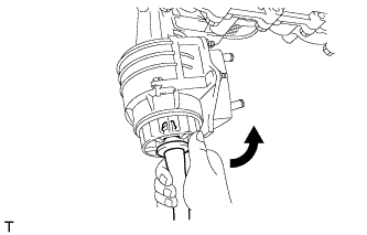
-
Check that oil is drained from the oil filter. Then disconnect the pipe and remove the O-ring as shown in the illustration.
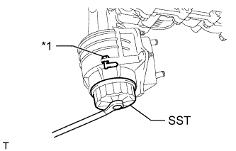
-
Using SST, remove the oil filter cap.
SST
09228-06501
Text in Illustration *1 Oil Filter Bracket Clip NOTICE:
Do not remove the oil filter bracket clip.
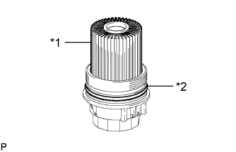
-
Remove the oil filter element and O-ring from the oil filter cap.
Text in Illustration *1 Oil Filter Element *2 O-Ring NOTICE:
Be sure to remove the cap O-ring by hand, without using any tools, to prevent damage to the cap O-ring groove.
| 34. REMOVE ENGINE OIL LEVEL DIPSTICK GUIDE |
-
Disconnect the wire harness clamp.
-
Remove the dipstick.
-
Remove the bolt and dipstick guide.
-
Remove the O-ring from the dipstick guide.
| 35. REMOVE OIL PRESSURE SENDER GAUGE ASSEMBLY |
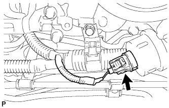
-
Disconnect the sender gauge connector.
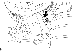
-
Remove the oil pressure sender gauge.
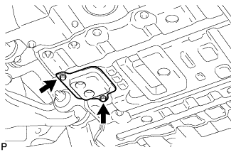
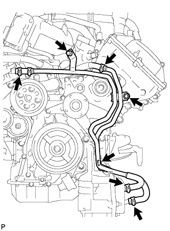
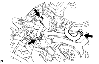
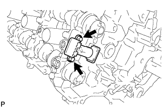
| 36. REMOVE NO. 2 WATER BY-PASS PIPE SUB-ASSEMBLY |
-
Remove the 3 bolts.
-
Disconnect the 4 hoses and remove the water by-pass pipe.
| 37. REMOVE NO. 1 OIL COOLER BRACKET |
-
Remove the 2 nuts and bracket.
-
Disconnect the ground wire from the cylinder block.
| 38. REMOVE OIL FILTER BRACKET |
-
Connect a hose with an inside diameter of 15 mm (0.591 in.) to the pipe.
Text in Illustration *1 Pipe *2 Hose
-
Remove the oil filter drain plug.
-
Install the pipe to the oil filter cap.
Text in Illustration *1 Cap *2 Valve *3 Pipe *4 O-Ring *5 Hose NOTICE:
If the O-ring is removed with the drain plug, install the O-ring together with the pipe.
HINT:
Use a container to catch the draining oil.
-
Check that oil is drained from the oil filter. Then disconnect the pipe and remove the O-ring as shown in the illustration.
-
Using SST, remove the oil filter cap.
SST
09228-06501
Text in Illustration *1 Oil Filter Bracket Clip NOTICE:
Do not remove the oil filter bracket clip.
-
Remove the oil filter element and O-ring from the oil filter cap.
Text in Illustration *1 Oil Filter Element *2 O-Ring NOTICE:
Be sure to remove the cap O-ring by hand, without using any tools, to prevent damage to the cap O-ring groove.
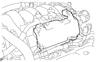
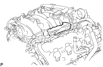
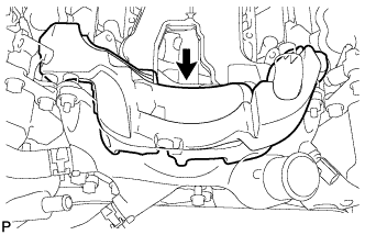
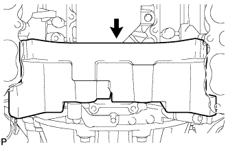
| 39. REMOVE INTAKE MANIFOLD |
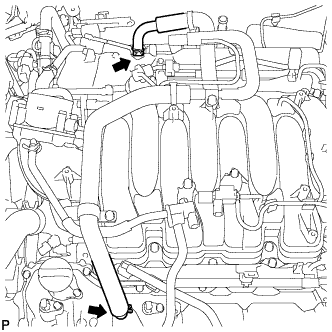
-
Disconnect the ventilation hose from the ventilation pipe of the cylinder head cover LH and RH.
-
Disconnect the 2 water by-pass hoses.
-
Disconnect the throttle body connector.
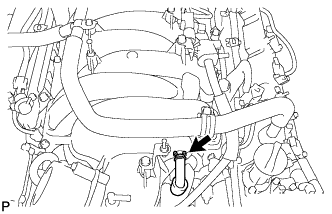
-
Disconnect the No. 1 ventilation hose.
-
Disconnect the purge VSV connector.
-
Disconnect the purge line hose from the purge VSV.
-
Disconnect the vacuum switching valve connector (for ACIS).
-
Remove the No. 1 engine cover sub-assembly.
-
Remove the No. 3 engine cover.
-
Disconnect the 3 wire clamps from the 3 wire brackets.
-
Remove the bolt and wire bracket from the intake manifold.
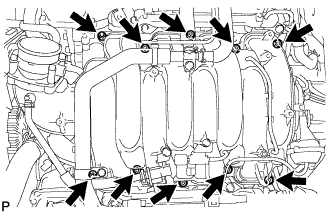
-
Remove the 2 nuts, 8 bolts, intake manifold and 2 gaskets.
| 40. DISCONNECT VANE PUMP ASSEMBLY |
-
Remove the 2 bolts and disconnect the vane pump.
| 41. DISCONNECT OIL COOLER PIPE ASSEMBLY |
-
Remove the 2 bolts and disconnect the oil cooler pipe.
| 42. REMOVE GENERATOR ASSEMBLY |
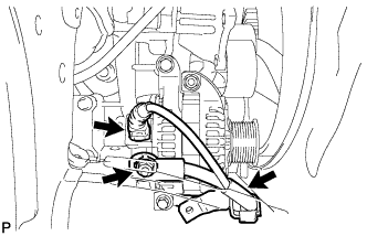
-
Disconnect the generator connector.
-
Remove the terminal cap and nut, and disconnect the generator wire.
-
Remove the bolt and wire harness bracket from the generator.
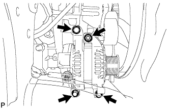
-
Remove the 3 bolts, nut and generator.
-
Remove the stud bolt.
| 43. REMOVE NO. 1 WATER BY-PASS HOSE |
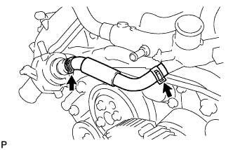
-
Remove the No. 1 water by-pass hose by disconnecting the hose from the water inlet housing and front water by-pass joint.
| 44. REMOVE WATER BY-PASS PIPE SUB-ASSEMBLY |
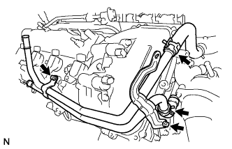
-
Disconnect the 2 hoses.
-
Remove the 2 bolts and water by-pass pipe.
| 45. REMOVE FRONT WATER BY-PASS JOINT |
-
Disconnect the No. 2 water by-pass hose from the water by-pass joint.
-
Remove the 4 nuts, water by-pass joint and 2 gaskets.
| 46. REMOVE NO. 2 ENGINE COVER |
| 47. REMOVE NO. 1 ENGINE COVER |
| 48. REMOVE WATER INLET HOUSING |
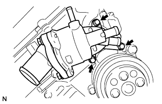
-
Remove the 3 bolts, water inlet housing and gasket.
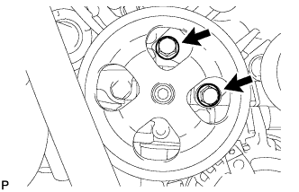
| 49. REMOVE WATER PUMP PULLEY |
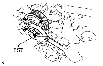
-
Using SST, hold the water pump pulley.
SST
09960-10010 (09962-01000,09963-01000)
-
Remove the 4 bolts and water pump pulley.
| 50. REMOVE NO. 1 IDLER PULLEY SUB-ASSEMBLY |
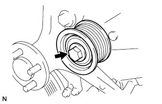
-
Remove the bolt and idler pulley.
| 51. REMOVE FLUID COUPLING BRACKET |
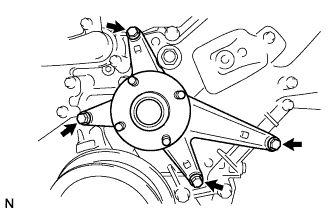
-
Remove the 4 bolts and fluid coupling bracket.
| 52. REMOVE V-RIBBED BELT TENSIONER ASSEMBLY |
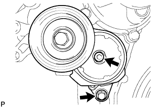
-
Remove the standard bolt, 6 mm hexagon wrench bolt and belt tensioner.
| 53. REMOVE IGNITION COIL ASSEMBLY |
-
Remove the 8 bolts and 8 ignition coils.
| 54. REMOVE CYLINDER HEAD COVER SUB-ASSEMBLY LH |
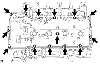
-
Remove the 14 bolts, seal washer, cylinder head cover and gasket.
HINT:
Make sure the removed parts are returned to the same places they were removed from.
-
Remove the 5 gaskets from the camshaft bearing caps (No. 2, No. 3).
| 55. REMOVE CYLINDER HEAD COVER SUB-ASSEMBLY RH |
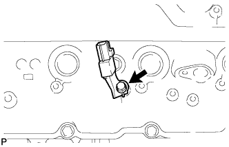
-
Remove the bolt and noise filter.
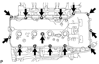
-
Remove the 14 bolts, seal washer, cylinder head cover and gasket.
HINT:
Make sure the removed parts are returned to the same places they were removed from.
-
Remove the 5 gaskets from the camshaft bearing caps (No. 1, No. 3).
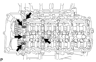
| 56. REMOVE SPARK PLUG TUBE GASKET |
-
Bend the 4 ventilation baffle plate claws on the cylinder head cover to an angle of 90° or more.
-
Using a screwdriver, pry out the gaskets.
Text in Illustration *1 Tape 
Pry NOTICE:
- Be careful not to damage the cylinder head cover.
- Be careful not to damage the gasket when removing it, as the removed gasket needs to be used when installing a new one.
HINT:
Tape the screwdriver tip before use.
| 57. REMOVE CRANKSHAFT PULLEY |
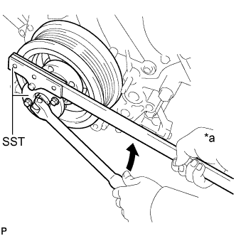
-
Using SST, loosen the crankshaft pulley set bolt until 2 or 3 threads are engaged.
SST
09213-70011 09330-00021
Text in Illustration *a Hold Turn
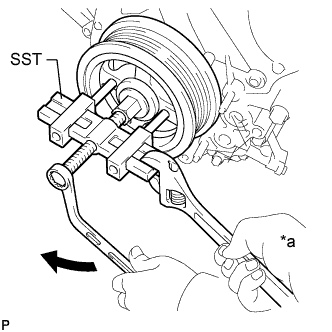
-
Using the pulley set bolt and SST, remove the crankshaft pulley.
SST
09950-50013 (09951-05010,09952-05010,09953-05010,09954-05011)
Text in Illustration *a Hold Turn
| 58. DISCONNECT WIRE HARNESS CLAMP BRACKET |
-
Remove the bolt and disconnect the bracket.
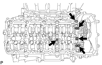
| 59. REMOVE TIMING CHAIN COVER SUB-ASSEMBLY |
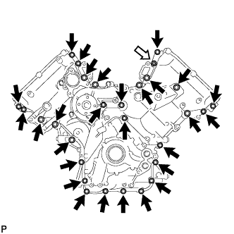
-
Remove the 28 bolts and nut shown in the illustration.
Text in Illustration Bolt 
Nut
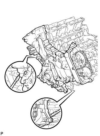
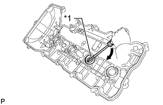
-
Remove the timing chain cover by prying between the timing chain cover and cylinder head or cylinder block with a screwdriver as shown in the illustration.
NOTICE:
Be careful not to damage the contact surfaces of the cylinder head, cylinder block and chain cover.
HINT:
Tape the screwdriver tip before use.
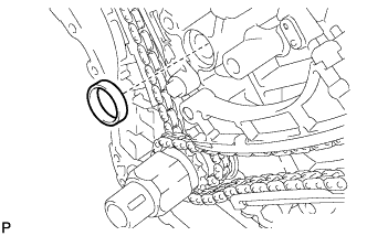
-
Remove the oil pump gasket from the cylinder block.
-
Remove the O-ring from the oil pan.
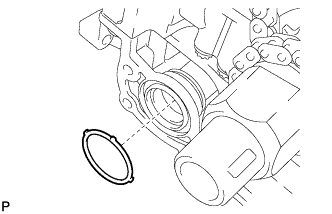
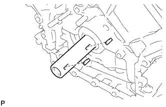
| 60. REMOVE WATER INLET PIPE |
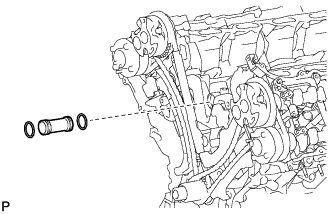
-
Remove the water inlet pipe.
-
Remove the 2 O-rings from the water inlet pipe.
| 61. SET NO. 1 CYLINDER TO TDC/COMPRESSION |
-
Temporarily install the crankshaft pulley bolt.
-
Rotate the crankshaft clockwise so that the timing marks on the crankshaft timing sprocket and camshaft timing gears are as shown in the illustration.
HINT:
If the timing marks do not align, rotate the crankshaft clockwise again and align the timing marks.
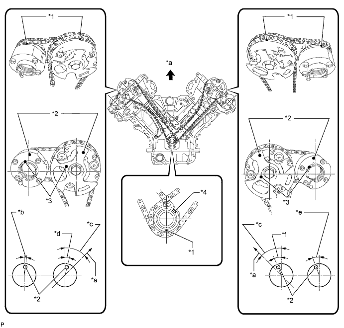
Text in Illustration *1 Timing Mark *2 Timing Mark Position *3 Knock Pin Position *4 Key *a Toward Ceiling *b Approximately 2° *c Approximately 45° *d Approximately 16° *e Approximately 18° *f Approximately 32°
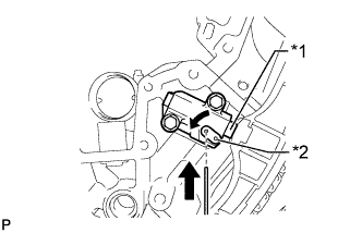
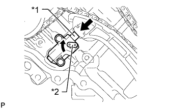
| 62. REMOVE NO. 1 CHAIN TENSIONER ASSEMBLY LH |
-
Move the stopper plate clockwise to release the lock, and push the plunger deep into the tensioner.
Text in Illustration *1 Plunger *2 Stopper Plate
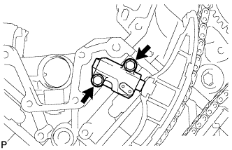
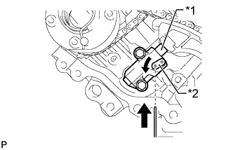
-
Move the stopper plate counterclockwise to set the lock, and insert a hexagon wrench into the stopper plate hole.
Text in Illustration *1 Plunger *2 Stopper Plate
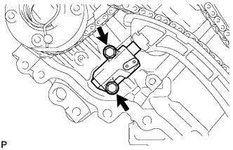
-
Remove the 2 bolts, chain tensioner and gasket.
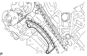
| 63. REMOVE NO. 1 CHAIN TENSIONER SLIPPER LH |
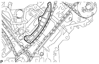
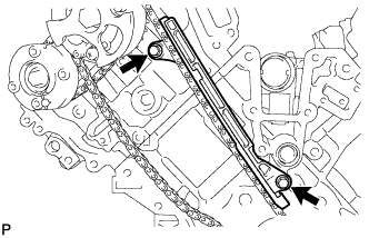
| 64. REMOVE NO. 1 CHAIN VIBRATION DAMPER LH |
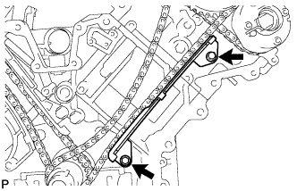
-
Remove the 2 bolts and chain vibration damper.
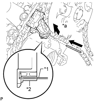
| 65. REMOVE NO. 1 CHAIN SUB-ASSEMBLY LH |
-
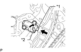
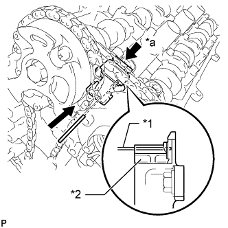
While pushing down the No. 3 chain tensioner, insert a pin of 1.0 mm (0.0394 in.) into the hole to fix it in place.
Text in Illustration *1 Pin *2 Plunger *a Push
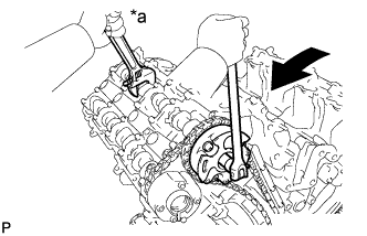
-
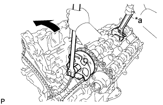
Hold the hexagonal portion of the camshaft with a wrench and loosen the bolt.
Text in Illustration *a Hold Turn NOTICE:
- Be careful not to damage the cylinder head with the wrench.
- Do not disassemble the camshaft timing gear.
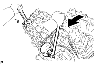
-
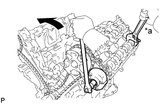
Hold the hexagonal portion of the camshaft with a wrench and loosen the bolt.
Text in Illustration *a Hold Turn NOTICE:
Be careful not to damage the cylinder head with the wrench.
-
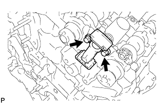
Remove the 2 bolts. Then with the No. 1 and No. 2 chains still connected to the gears, remove the camshaft timing gear, camshaft timing exhaust gear and crankshaft timing sprocket LH.
-
Remove the No. 1 and No. 2 chains from the gears.
| 66. REMOVE NO. 3 CHAIN TENSIONER ASSEMBLY |
-
Remove the 2 bolts and chain tensioner.
| 67. REMOVE NO. 1 CHAIN TENSIONER ASSEMBLY RH |
-
Move the stopper plate clockwise to release the lock, and push the plunger deep into the tensioner.
Text in Illustration *1 Plunger *2 Stopper Plate
-
Move the stopper plate counterclockwise to set the lock, and insert a hexagon wrench into the stopper plate hole.
Text in Illustration *1 Plunger *2 Stopper Plate
-
Remove the 2 bolts and chain tensioner.
| 68. REMOVE NO. 1 CHAIN TENSIONER SLIPPER RH |
| 69. REMOVE NO. 1 CHAIN VIBRATION DAMPER RH |
-
Remove the 2 bolts and vibration damper.
| 70. REMOVE NO. 1 CHAIN SUB-ASSEMBLY RH |
-
While raising up the No. 2 chain tensioner, insert a pin of 1.0 mm (0.0394 in.) into the hole to fix it in place.
Text in Illustration *1 Pin *2 Plunger *a Push
-
Hold the hexagonal portion of the camshaft with a wrench and loosen the bolt.
Text in Illustration *a Hold Turn NOTICE:
- Be careful not to damage the cylinder head with the wrench.
- Do not disassemble the camshaft timing gear.
-
Hold the hexagonal portion of the camshaft with a wrench and loosen the bolt.
Text in Illustration *a Hold Turn NOTICE:
Be careful not to damage the cylinder head with the wrench.
-
Remove the 2 bolts. Then with the No. 1 and No. 2 chains still connected to the gears, remove the camshaft timing gear, camshaft timing exhaust gear and crankshaft timing sprocket RH.
-
Remove the No. 1 and No. 2 chains from the gears.
| 71. REMOVE NO. 2 CHAIN TENSIONER ASSEMBLY |
-
Remove the 2 bolts and chain tensioner.
| 72. REMOVE CRANKSHAFT TIMING GEAR KEY |
-
Using a screwdriver, remove the 2 timing gear keys from the crankshaft.
| 73. REMOVE CAMSHAFT BEARING CAP LH |
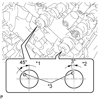
-
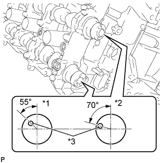
Make sure that the knock pin of the camshaft is positioned as shown in the illustration.
Text in Illustration *1 IN *2 EX *3 Knock Pin
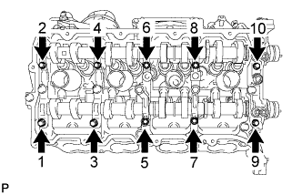
-
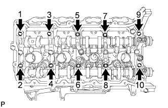
Uniformly loosen and remove the 10 bearing cap bolts in the sequence shown in the illustration.
-
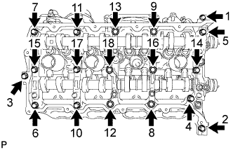
Uniformly loosen and remove the 18 bearing cap bolts in the sequence shown in the illustration.
NOTICE:
Uniformly loosen the bolts while keeping the camshaft level.
-
Remove the 6 bearing caps.
HINT:
Arrange the removed parts in the correct order.
-
Remove the No. 3 and No. 4 camshafts.
| 74. REMOVE CAMSHAFT HOUSING SUB-ASSEMBLY LH |
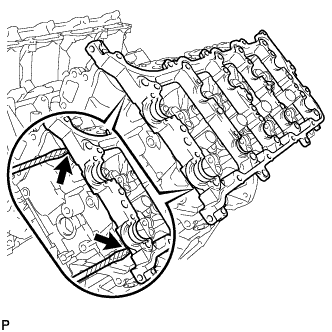
-
Remove the camshaft housing by prying between the cylinder head and camshaft housing with a screwdriver.
NOTICE:
Be careful not to damage the contact surfaces of the cylinder head and camshaft housing.
HINT:
Tape the screwdriver tip before use.
| 75. REMOVE CAMSHAFT BEARING CAP RH |
-
Make sure that the knock pin of the camshaft is positioned as shown in the illustration.
Text in Illustration *1 EX *2 IN *3 Knock Pin
-
Uniformly loosen and remove the 10 bearing cap bolts in the sequence shown in the illustration.
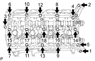
-
Uniformly loosen and remove the 18 bearing cap bolts in the sequence shown in the illustration.
NOTICE:
Uniformly loosen the bolts while keeping the camshaft level.
-
Remove the 6 bearing caps.
HINT:
Arrange the removed parts in the correct order.
-
Remove the No. 1 and No. 2 camshafts.
| 76. REMOVE CAMSHAFT HOUSING SUB-ASSEMBLY RH |
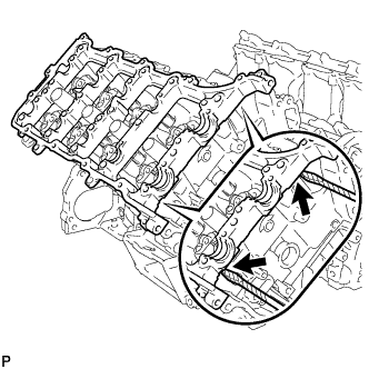
-
Remove the camshaft housing by prying between the cylinder head and camshaft housing with a screwdriver.
NOTICE:
Be careful not to damage the contact surfaces of the cylinder head and camshaft housing.
HINT:
Tape the screwdriver tip before use.