Блок Механической Трансмиссии В Блоке С Главной Передачей Повторная Сборка. Corolla ZZE150
INSTALL SHIFT AND SELECT LEVER SHAFT SLIDE BALL BEARING
INSTALL SHIFT AND SELECT LEVER SHAFT OIL SEAL
INSTALL OUTPUT SHAFT (MTM) COVER
INSTALL TRANSMISSION CASE OIL SEAL
INSTALL TRANSAXLE CASE OIL SEAL
INSTALL FRONT DIFFERENTIAL CASE FRONT TAPERED ROLLER BEARING
INSTALL FRONT DIFFERENTIAL CASE REAR TAPERED ROLLER BEARING
INSTALL OUTPUT SHAFT FRONT BEARING
ADJUST DIFFERENTIAL SIDE BEARING PRELOAD
INSTALL FRONT TRANSAXLE CASE OIL SEAL
INSTALL INPUT SHAFT FRONT BEARING
INSTALL TRANSMISSION MAGNET
INSTALL BEARING LOCK PLATE
INSTALL MANUAL TRANSAXLE CASE RECEIVER
INSTALL DIFFERENTIAL CASE ASSEMBLY
INSTALL REVERSE SHIFT ARM BRACKET ASSEMBLY
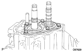
INSTALL INPUT SHAFT ASSEMBLY
INSTALL REVERSE IDLER GEAR SUB-ASSEMBLY
INSTALL NO. 2 GEAR SHIFT FORK SHAFT
INSTALL NO. 3 GEAR SHIFT FORK SHAFT
INSTALL NO. 1 GEAR SHIFT FORK SHAFT SUB-ASSEMBLY
INSTALL NO. 2 OIL RECEIVER PIPE (MTM)
INSTALL NO. 1 OIL RECEIVER PIPE (MTM)
INSTALL MANUAL TRANSMISSION CASE
INSTALL REVERSE IDLER GEAR SHAFT BOLT
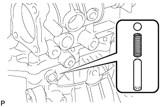
INSTALL REVERSE RESTRICT PIN PLUG
INSTALL INPUT SHAFT REAR BEARING HOLE SNAP RING
INSTALL OUTPUT SHAFT REAR BEARING HOLE SNAP RING
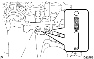
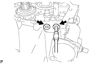
INSTALL SHIFT DETENT BALL
INSTALL BEARING RETAINER REAR (MTM)
INSTALL SHIFT FORK SHAFT SNAP RING
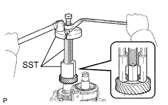
INSTALL 5TH DRIVEN GEAR
INSTALL 5TH GEAR NEEDLE ROLLER BEARING
INSTALL 5TH GEAR
INSTALL NO. 3 SYNCHRONIZER RING (for 5th Gear)
INSTALL NO. 3 TRANSMISSION CLUTCH HUB
INSTALL NO. 3 SYNCHRONIZER RING (for 6th Gear)
INSTALL 6TH GEAR NEEDLE ROLLER BEARING
INSTALL 6TH GEAR SUB-ASSEMBLY
INSTALL OUTPUT GEAR SPACER
INSTALL 6TH COUNTER GEAR
INSPECT 6TH GEAR THRUST CLEARANCE
INSPECT 5TH GEAR THRUST CLEARANCE
INSPECT 6TH GEAR RADIAL CLEARANCE
INSPECT 5TH GEAR RADIAL CLEARANCE
INSTALL MANUAL TRANSMISSION CASE COVER SUB-ASSEMBLY
INSTALL MANUAL TRANSMISSION CASE PLUG
INSTALL SHIFT AND SELECT LEVER SHAFT ASSEMBLY
INSTALL SHIFT GATE PIN
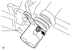
INSTALL NO. 1 LOCK BALL ASSEMBLY
INSTALL FLOOR SHIFT CONTROL SHIFT LEVER
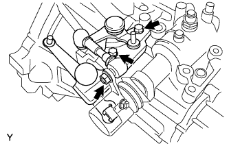
INSTALL SELECTING BELL CRANK ASSEMBLY
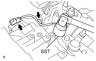
INSTALL BACK-UP LIGHT SWITCH ASSEMBLY
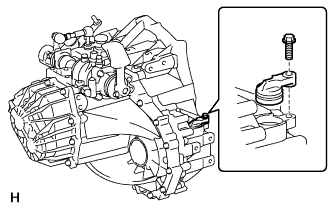
INSTALL SPEEDOMETER DRIVEN HOLE COVER SUB-ASSEMBLY
INSTALL DRAIN (MTM) PLUG SUB-ASSEMBLY
INSTALL MANUAL TRANSMISSION FILLER PLUG
Блок Механической Трансмиссии В Блоке С Главной Передачей -- Повторная Сборка |
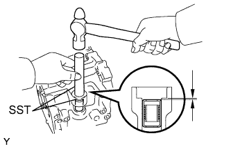
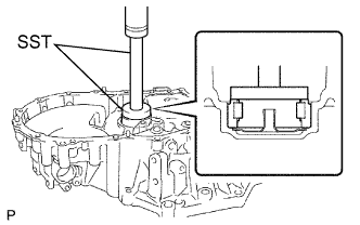
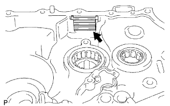
| 1. INSTALL SHIFT AND SELECT LEVER SHAFT SLIDE BALL BEARING |
Using SST and a hammer, install the shift and select lever shaft slide ball bearing onto the transmission case.
- SST
- 09950-60010(09951-00220)
09950-70010(09951-07100)
- Drive in depth:
- 0 to 0.5 mm (0 to 0.020 in.)
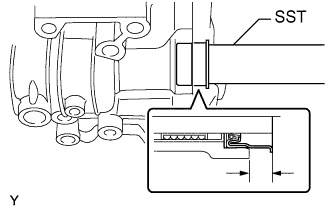
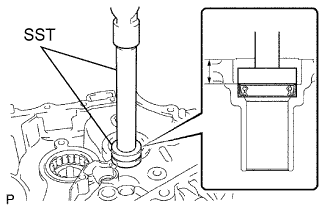
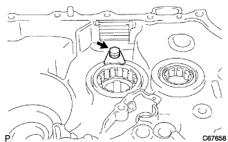
| 2. INSTALL SHIFT AND SELECT LEVER SHAFT OIL SEAL |
Using SST, install the shift and select lever shaft oil seal onto the transmission case.
- SST
- 09950-60010(09951-00240)
09950-70010(09951-00240)
- Drive in depth:
- 9.7 to 10.3 mm (0.382 to 0.406 in.)
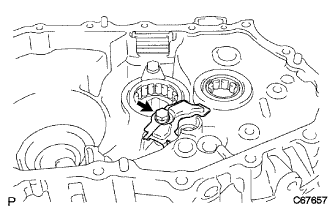
| 3. INSTALL OUTPUT SHAFT (MTM) COVER |
Coat the output shaft (MTM) cover with MP grease and install it onto the front transaxle case.
- ПРИМЕЧАНИЕ:
- Insert the output shaft cover projection into the case side hollow.
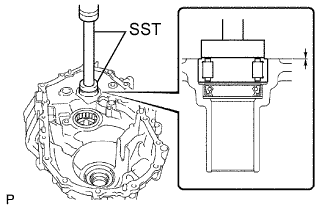
| 4. INSTALL TRANSMISSION CASE OIL SEAL |
Using SST and a hammer, install a new transmission case oil seal onto the manual transmission case.
- SST
- 09316-60011(09316-00011)
- Drive in depth:
- 9.6 to 10.2 mm (0.378 to 0.402 in.)
Coat the lip of the front transmission case oil seal with MP grease.
| 5. INSTALL TRANSAXLE CASE OIL SEAL |
Using SST and a hammer, install a new transaxle case oil seal onto the front transaxle case.
- Drive in depth:
- 1.6 to 2.2 mm (0.063 to 0.087 in.)
- SST
- 09710-20011(09710-06071)
09950-70010(09951-07150)
Coat the lip of the transaxle case oil seal with MP grease.
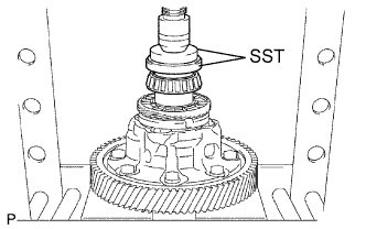
| 6. INSTALL FRONT DIFFERENTIAL CASE FRONT TAPERED ROLLER BEARING |
Using SST and a press, install a new front differential case front tapered roller bearing (inner race) to the front differential case.
- SST
- 09350-32014(09351-32120)
09950-60010(09951-00530)
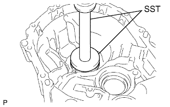
Using SST and a press, install the front differential case front plate washer and front differential case front tapered roller bearing (outer race) to the transaxle case.
- SST
- 09950-60020(09951-00680)
09950-70010(09951-07150)
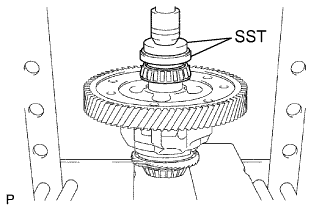
| 7. INSTALL FRONT DIFFERENTIAL CASE REAR TAPERED ROLLER BEARING |
Using SST and a press, install a new front differential case rear tapered roller bearing (inner race) to the front differential case.
- SST
- 09350-32014(09351-32120)
09950-60010(09951-00530)
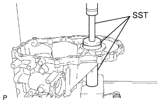
Using SST and a press, install the front differential case rear plate washer and front differential case rear tapered roller bearing (outer race) to the manual transmission case.
- SST
- 09309-36010
09950-60020(09951-00710)
09950-70010(09951-07150)
| 8. INSTALL OUTPUT SHAFT FRONT BEARING |
Coat a new output shaft front bearing with gear oil, and using SST and a press, install it to the transaxle case.
- SST
- 09950-60010(09951-00550)
09950-70010(09951-07150)
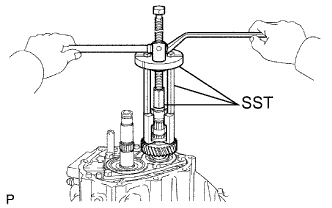
| 9. ADJUST DIFFERENTIAL SIDE BEARING PRELOAD |
Coat the differential case assembly with gear oil, and install it to the transaxle case.
Install the manual transmission case with the 16 bolts.
- Момент затяжки:
- 29 Н*м{300 кгс*см, 22 фунт-сила-футов}
Using SST and a torque wrench, turn the differential case assembly right and left 2 or 3 times to allow the bearings to settle.
- SST
- 09564-32011
Using SST and a torque wrench, measure the preload.
- SST
- 09564-32011
Preload:Bearing
| Torque
|
New
| 0.78 to 1.57 N*m (8 to 16 kgf*cm, 7 to 14 in.*lbf)
|
Used
| 0.49 to 0.98 N*m (5 to 10 kgf*cm, 4 to 9 in.*lbf)
|
- УКАЗАНИЕ:
- If the preload is out of specification, select a proper front differential case rear plate washer and adjust it.
Washer thickness:Part No.
| Thickness: mm (in.)
| Mark
|
90564-41014
| 2.10 (0.0827)
| AA
|
90564-41015
| 2.15 (0.0846)
| BB
|
90564-41016
| 2.20 (0.0866)
| CC
|
90564-41017
| 2.25 (0.0886)
| DD
|
90564-41018
| 2.30 (0.0906)
| EE
|
90564-41019
| 2.35 (0.0925)
| FF
|
90564-41020
| 2.40 (0.0945)
| GG
|
90564-41021
| 2.45 (0.0965)
| HH
|
90564-41022
| 2.50 (0.0984)
| JJ
|
90564-41023
| 2.55 (0.1004)
| KK
|
90564-41024
| 2.60 (0.1024)
| LL
|
90564-41025
| 2.65 (0.1043)
| MM
|
90564-41026
| 2.70 (0.1063)
| NN
|
90564-41027
| 2.75 (0.1083)
| PP
|
90564-41028
| 2.80 (0.1102)
| QQ
|
90564-41029
| 2.85 (0.1122)
| RR
|
90564-41030
| 2.90 (0.1142)
| SS
|
90564-41031
| 2.95 (0.1161)
| TT
|
90564-41032
| 3.00 (0.1181)
| UU
|
Remove the 16 bolts and manual transmission case.
Remove the differential case assembly from the transaxle case.
| 10. INSTALL FRONT TRANSAXLE CASE OIL SEAL |
Using SST and a hammer, install a new front transaxle case oil seal to the transaxle case.
- SST
- 09950-60010(09951-00370)
09950-70010(09951-07150)
- Driven in depth:
- 15.6 to 16.0 mm (0.6142 to 0.6299 in.)
Coat the lip of the front transaxle case oil seal with MP grease.
| 11. INSTALL INPUT SHAFT FRONT BEARING |
Coat a new input shaft front bearing with gear oil, and using SST and a press, install it to the transaxle case.
- SST
- 09950-60010(09951-00420)
09950-70010(09951-07150)
- Driven in depth:
- 0 to 0.30 mm (0 to 0.0118 in.)
| 12. INSTALL TRANSMISSION MAGNET |
Clean the transmission magnet, and install it to the transaxle case.
| 13. INSTALL BEARING LOCK PLATE |
Install the bearing lock plate with the bolt to the transaxle case.
- Момент затяжки:
- 11 Н*м{115 кгс*см, 8 фунт-сила-футов}
| 14. INSTALL MANUAL TRANSAXLE CASE RECEIVER |
Install the manual transaxle case receiver with the bolt to the transaxle case.
- Момент затяжки:
- 11 Н*м{115 кгс*см, 8 фунт-сила-футов}
| 15. INSTALL DIFFERENTIAL CASE ASSEMBLY |
Coat the differential case tapered roller bearing with gear oil, and install the differential case assembly to the transaxle case.
| 16. INSTALL REVERSE SHIFT ARM BRACKET ASSEMBLY |
Install the reverse shift arm bracket assembly with the 2 bolts to the transaxle case.
- Момент затяжки:
- 17 Н*м{175 кгс*см, 13 фунт-сила-футов}
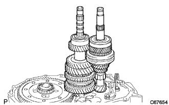
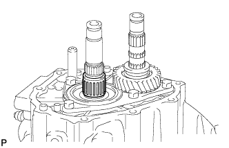
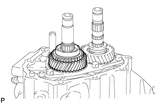
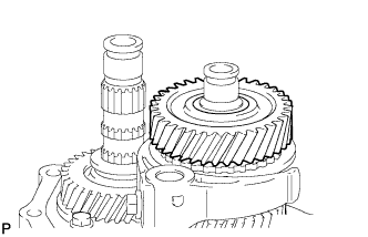
| 17. INSTALL INPUT SHAFT ASSEMBLY |
Coat the sliding and rotating surfaces of the input shaft assembly and output shaft assembly with gear oil, and install them to the transaxle case.
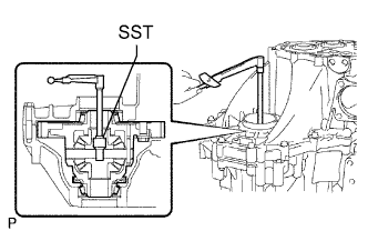
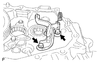
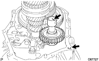
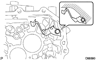
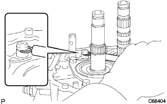
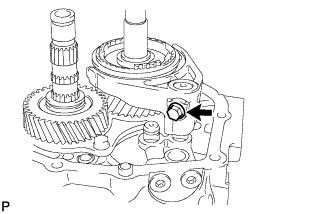
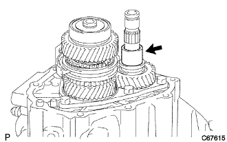
| 18. INSTALL REVERSE IDLER GEAR SUB-ASSEMBLY |
Coat the reverse idler gear sub-assembly, thrust washer and reverse idler gear shaft with gear oil, and install them to the transaxle case.
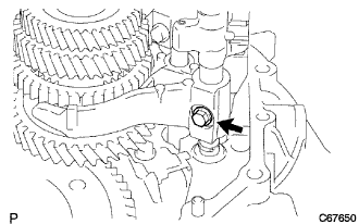
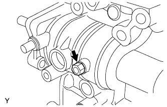
- УКАЗАНИЕ:
- Align the mark on the reverse idler gear shaft with the bolt hole shown in the illustration.
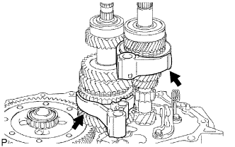
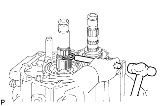
| 19. INSTALL NO. 2 GEAR SHIFT FORK SHAFT |
Coat the No. 2 gear shift fork and No. 1 gear shift fork with gear oil, and install them to the input shaft assembly and output shaft assembly.
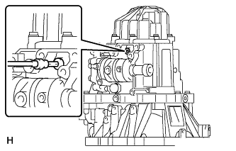
Coat the No. 2 gear shift fork shaft with gear oil, and install the No. 1 gear shift head, reverse shift fork and No. 2 gear shift fork shaft.
Coat the 2 shift lock bolts with sealant, and install them to the No. 2 gear shift fork and No. 1 gear shift head.
- Sealant:
- Toyota Genuine Adhesive 1344, Three Bond 1344 or equivalent
- Момент затяжки:
- 16 Н*м{160 кгс*см, 12 фунт-сила-футов}
| 20. INSTALL NO. 3 GEAR SHIFT FORK SHAFT |
Using a brass bar and a hammer, install a new shaft snap ring to the No. 3 gear shift fork shaft.
Coat the No. 3 gear shift fork shaft with gear oil, and install it to the transaxle case.
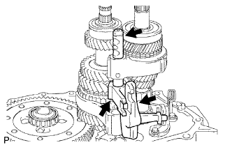
| 21. INSTALL NO. 1 GEAR SHIFT FORK SHAFT SUB-ASSEMBLY |
Coat the No. 1 gear shift fork shaft sub-assembly with gear oil, and install it to the transaxle case.
Coat the shift fork lock bolt with sealant, and install it to the No. 1 gear shift fork.
- Sealant:
- Toyota Genuine Adhesive 1344, Three Bond 1344 or equivalent
- Момент затяжки:
- 16 Н*м{160 кгс*см, 12 фунт-сила-футов}
Using a brass bar and a hammer, install a new shaft snap ring.
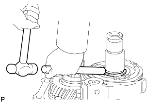
| 22. INSTALL NO. 2 OIL RECEIVER PIPE (MTM) |
Install the No. 2 oil receiver pipe (MTM) with the bolt to the manual transmission case.
- Момент затяжки:
- 17 Н*м{175 кгс*см, 13 фунт-сила-футов}
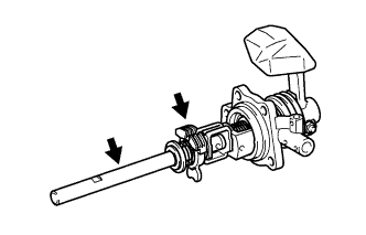
- ПРИМЕЧАНИЕ:
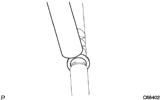
- Do not deform the No. 2 oil receiver pipe.
- Install the No. 2 oil receiver pipe while holding it against the manual transmission case as shown in the illustration.
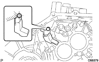
| 23. INSTALL NO. 1 OIL RECEIVER PIPE (MTM) |
Install the No. 1 oil receiver pipe (MTM) with the bolt to the manual transmission case.
- Момент затяжки:
- 17 Н*м{175 кгс*см, 13 фунт-сила-футов}
- ПРИМЕЧАНИЕ:
- Do not deform the No. 1 oil receiver pipe.
- Install the No. 1 oil receiver pipe while holding it against the manual transmission case as shown in the illustration.
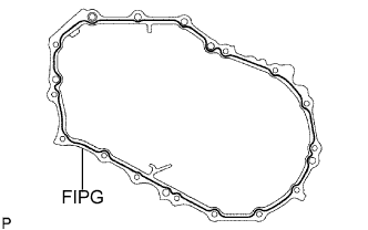
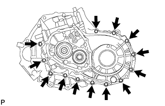
| 24. INSTALL MANUAL TRANSMISSION CASE |
Apply FIPG to the manual transmission case, as shown in the illustration.
- FIPG:
- Toyota Genuine Seal Packing 1281, Three Bond 1281 or equivalent
- ПРИМЕЧАНИЕ:
- Assemble the parts within 10 minutes of application. Otherwise, the packing (FIPG) material must be removed and reapplied.
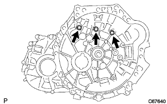
Install the 13 bolts to the manual transmission side.
- Момент затяжки:
- 29 Н*м{300 кгс*см, 22 фунт-сила-футов}
Coat the 3 bolts with sealant and install them onto the manual transaxle side.
- Sealant:
- Toyota Genuine Adhesive 1344, Three Bond 1344 or equivalent
- Момент затяжки:
- 29 Н*м{300 кгс*см, 22 фунт-сила-футов}
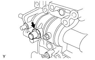
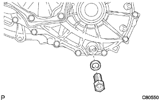
| 25. INSTALL REVERSE IDLER GEAR SHAFT BOLT |
Coat the reverse idler gear shaft bolt with sealant, and install it with a new gasket to the manual transmission case.
- Sealant:
- Toyota Genuine Adhesive 1344, Three Bond 1344 or equivalent
- Момент затяжки:
- 29 Н*м{300 кгс*см, 22 фунт-сила-футов}
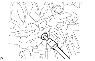
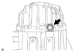
| 26. INSTALL REVERSE RESTRICT PIN PLUG |
Coat the transmission case plug with sealant, and using a socket hexagon wrench (6 mm), install it to the manual transmission case.
- Sealant:
- Toyota Genuine Adhesive 1344, Three Bond 1344 or equivalent
- Момент затяжки:
- 29 Н*м{296 кгс*см, 21 фунт-сила-футов}
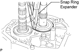
| 27. INSTALL INPUT SHAFT REAR BEARING HOLE SNAP RING |
Using a snap ring expander, install the input shaft rear bearing hole snap ring to the input shaft assembly.
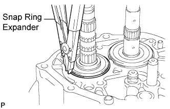
| 28. INSTALL OUTPUT SHAFT REAR BEARING HOLE SNAP RING |
Using a snap ring expander, install the output shaft rear bearing hole snap ring to the output shaft assembly.
| 29. INSTALL SHIFT DETENT BALL |
Install the shift detent ball, shift detent ball compression spring and shift detent ball compression spring seat to the transaxle case.
Coat the shift detent ball plug with sealant, and using SST, install it to the transaxle case.
- Sealant:
- Toyota Genuine Adhesive 1344, Three Bond 1344 or equivalent
- Момент затяжки:
- 22 Н*м{224 кгс*см, 16 фунт-сила-футов}
Install the 2 shift detent balls, 2 shift detent ball springs and 2 shift detent ball spring seats to the manual transmission case.
Coat the 2 shift detent ball plugs with sealant, and install them to the manual transmission case.
- Sealant:
- Toyota Genuine Adhesive 1344, Three Bond 1344 or equivalent
- Момент затяжки:
- 22 Н*м{224 кгс*см, 16 фунт-сила-футов}
| 30. INSTALL BEARING RETAINER REAR (MTM) |
Coat the 5 bolts with sealant, and install the bearing retainer rear (MTM) to the manual transmission case with the bolts.
- Sealant:
- Toyota Genuine Adhesive 1344, Three Bond 1344 or equivalent
- Момент затяжки:
- 27 Н*м{279 кгс*см, 20 фунт-сила-футов}
| 31. INSTALL SHIFT FORK SHAFT SNAP RING |
Using a brass bar and a hammer, install a new shift fork shaft snap ring to the No. 2 shift fork shaft.
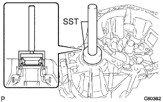
| 32. INSTALL 5TH DRIVEN GEAR |
Using SST, install the 5th driven gear to the output shaft assembly.
- SST
- 09950-30012(09951-03010,09953-03010,09954-03010,09955-03011,09956-03080)
| 33. INSTALL 5TH GEAR NEEDLE ROLLER BEARING |
Coat the two 5th gear bearing spacers and 5th gear needle roller bearing with gear oil, and install them to the input shaft assembly.
Using a brass bar and a hammer, install a new No. 3 transmission clutch hub shaft snap ring to the input shaft assembly.
Coat the 5th gear with gear oil, and install it to the input shaft.
| 35. INSTALL NO. 3 SYNCHRONIZER RING (for 5th Gear) |
Coat the No. 3 synchronizer ring with gear oil, and install it to the 5th gear.
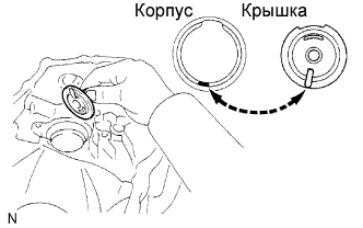
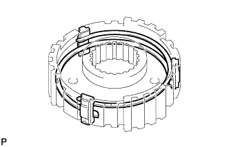
| 36. INSTALL NO. 3 TRANSMISSION CLUTCH HUB |
Install the 3 synchromesh shifting keys and 2 synchromesh shifting key springs onto the No. 3 transmission clutch hub, as shown in the illustration.
- ПРИМЕЧАНИЕ:
- Do not set the 2 shifting key spring openings in the same position.
Install the No. 3 transmission hub sleeve to the No. 3 transmission clutch hub.
- ПРИМЕЧАНИЕ:
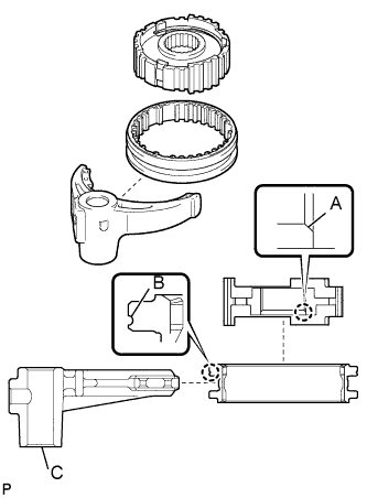
- Install the No. 3 transmission clutch hub with side A facing down. Install the No. 3 transmission hub sleeve with side B facing up.
Install the No. 3 gear shift fork to the No. 3 transmission clutch hub with No. 3 transmission hub sleeve.
- ПРИМЕЧАНИЕ:
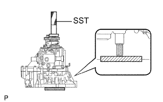
- Install the No. 3 gear shift fork with part C facing down.
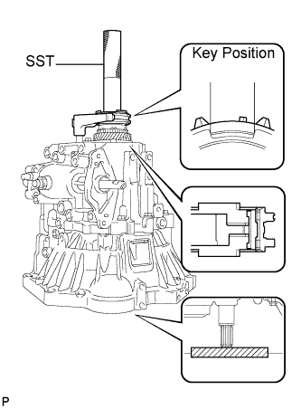
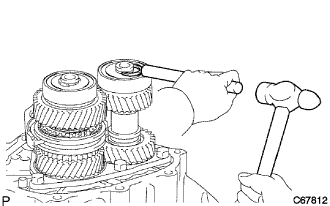
Using SST and a hammer, install the No. 3 transmission clutch hub with the No. 3 gear shift fork to the input shaft assembly.
- SST
- 09608-04031
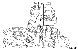
- ПРИМЕЧАНИЕ:
- Before driving in the No. 3 transmission clutch hub, place a suitable sized wooden block under the rear side of the input shaft assembly, as shown in the illustration.
- When driving it in, fix the input shaft firmly so that it is not pushed downward. Otherwise the input shaft rear bearing is over loaded and might be damaged.
Coat the shift fork lock bolt with sealant, and install it to the No. 3 gear shift fork.
- Момент затяжки:
- 16 Н*м{160 кгс*см, 12 фунт-сила-футов}
Select the snap ring that allows the minimum amount of axial play.
- Clearance:
- 0.1 mm (0.004 in.) or less
Snap ring thickness:Part No.
| Thickness: mm (in.)
| Mark
|
90520-20074
| 1.75 (0.0689)
| A
|
90520-20075
| 1.80 (0.0709)
| B
|
90520-20076
| 1.85 (0.0728)
| C
|
90520-20077
| 1.90 (0.0748)
| D
|
90520-20078
| 1.95 (0.0768)
| E
|
90520-20079
| 2.00 (0.0787)
| F
|
90520-20080
| 2.05 (0.0807)
| G
|
90520-20081
| 2.10 (0.0827)
| H
|
90520-20082
| 2.15 (0.0846)
| J
|
Using a brass bar and a hammer, install the transmission clutch hub No. 3 snap ring to the input shaft.
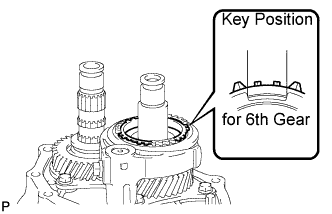
| 37. INSTALL NO. 3 SYNCHRONIZER RING (for 6th Gear) |
Coat the No. 3 synchronizer ring (for 6th gear) with gear oil, and install it to the No. 3 transmission clutch hub.
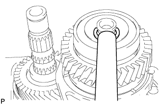
| 38. INSTALL 6TH GEAR NEEDLE ROLLER BEARING |
Coat the 6th gear needle roller bearing and 6th gear spacer with gear oil, and install them to the input shaft assembly.
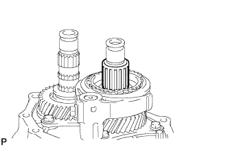
| 39. INSTALL 6TH GEAR SUB-ASSEMBLY |
Coat the 6th gear sub-assembly with gear oil, and install it to the input shaft assembly.
Using SST, a steel block and a hammer, install the input shaft rear radial ball bearing to the input shaft assembly.
- SST
- 09608-04031
Select the input shaft shaft snap ring that allows the minimum amount of axial play.
- Clearance:
- 0.1 mm (0.004 in.) or less
Snap ring thickness:Part No.
| Thickness: mm (in.)
| Mark
|
90520-17006
| 1.70 (0.0669)
| A
|
90520-17007
| 1.75 (0.0689)
| B
|
90520-17008
| 1.80 (0.0709)
| C
|
90520-17009
| 1.85 (0.0728)
| D
|
90520-17010
| 1.90 (0.0748)
| E
|
90520-17011
| 1.95 (0.0768)
| F
|
90520-17012
| 2.00 (0.0787)
| G
|
90520-17013
| 2.05 (0.0807)
| H
|
90520-17014
| 2.10 (0.0827)
| J
|
90520-17015
| 2.15 (0.0846)
| K
|
90520-17016
| 2.20 (0.0866)
| L
|
90520-17017
| 2.25 (0.0886)
| M
|
Using a brass bar and a hammer, install the input shaft shaft snap ring to the input shaft assembly.
| 40. INSTALL OUTPUT GEAR SPACER |
Install the output gear spacer to the output shaft assembly.
| 41. INSTALL 6TH COUNTER GEAR |
Using SST, install the 6th counter gear to the output shaft assembly.
- SST
- 09950-30012(09951-03010,09953-03010,09954-03010,09955-03011,09956-03080)
Using SST, install the output shaft rear bearing to the output shaft assembly.
- SST
- 09950-30012(09951-03010,09953-03010,09954-03010,09955-03011,09956-03080)
Select the output shaft rear snap ring that allows the minimum amount of axial play.
- Clearance:
- 0.1 mm (0.004 in.) or less
Snap ring thickness:Part No.
| Thickness: mm (in.)
| Mark
|
90520-18003
| 2.31 (0.0909)
| B
|
90520-18004
| 2.37 (0.0933)
| C
|
90520-18006
| 2.43 (0.0957)
| D
|
90520-18007
| 2.49 (0.0980)
| E
|
90520-18008
| 2.55 (0.1004)
| F
|
90520-18009
| 2.61 (0.1028)
| G
|
90520-18013
| 2.67 (0.1051)
| H
|
90520-18011
| 2.73 (0.1075)
| J
|
90520-18014
| 2.79 (0.1098)
| K
|
90520-18015
| 2.85 (0.1122)
| L
|
90520-18016
| 2.91 (0.1146)
| M
|
Using a brass bar and a hammer, install the output shaft rear snap ring to the output shaft assembly.
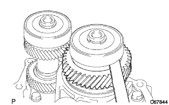
| 42. INSPECT 6TH GEAR THRUST CLEARANCE |
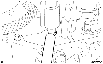
Using a feeler gauge, measure the 6th gear thrust clearance.
- Standard clearance:
- 0.10 to 0.60 mm (0.0039 to 0.0236 in.)
- Maximum clearance:
- 0.60 mm (0.0236 in.)
If the clearance exceeds the maximum, replace the No. 3 transmission clutch hub, the 6th gear or input shaft rear radial ball bearing.
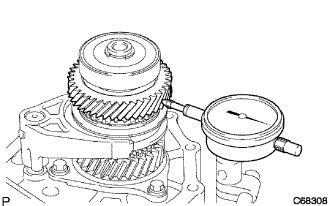
| 43. INSPECT 5TH GEAR THRUST CLEARANCE |
Using a dial indicator, measure the 5th gear thrust clearance.
- Standard clearance:
- 0.10 to 0.62 mm (0.0039 to 0.0244 in.)
- Maximum clearance:
- 0.62 mm (0.0244 in.)
If the clearance exceeds the maximum, replace the No. 3 transmission clutch hub, the 5th gear or input shaft rear radial ball bearing.
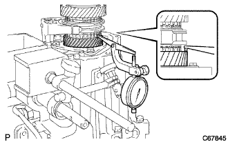
| 44. INSPECT 6TH GEAR RADIAL CLEARANCE |
Using a dial indicator, measure the 6th gear radial clearance.
- Standard clearance:
- 0.009 to 0.050 mm (0.0004 to 0.0020 in.)
- Maximum clearance:
- 0.050 mm (0.0020 in.)
- УКАЗАНИЕ:
- If the clearance exceeds the maximum, replace the 6th gear, 6th gear needle roller bearing or input shaft.
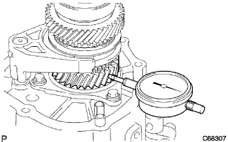
| 45. INSPECT 5TH GEAR RADIAL CLEARANCE |
Using a dial indicator, measure the 5th gear radial clearance.
- Standard clearance:
- 0.015 to 0.056 mm (0.0006 to 0.0022 in.)
- Maximum clearance:
- 0.056 mm (0.0022 in.)
- УКАЗАНИЕ:
- If the clearance exceeds the maximum, replace the 5th gear, 5th gear needle roller bearing or input shaft.
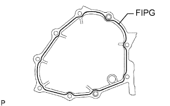
| 46. INSTALL MANUAL TRANSMISSION CASE COVER SUB-ASSEMBLY |
Apply FIPG to the manual transmission case cover sub-assembly as shown in the illustration.
- FIPG:
- Toyota Genuine Seal Packing 1281, Three Bond 1281 or equivalent
- ПРИМЕЧАНИЕ:
- Assemble the parts within 10 minutes of application. Otherwise, the packing (FIPG) material must be removed and reapplied.
Install the manual transmission case cover sub-assembly with the 9 bolts to the manual transmission case.
- Момент затяжки:
- 21 Н*м{214 кгс*см, 16 фунт-сила-футов}
| 47. INSTALL MANUAL TRANSMISSION CASE PLUG |
Coat the transmission case plug with sealant.
- Sealant:
- Toyota Genuine Adhesive 1344, Three Bond 1344 or equivalent
Using a socket hexagon wrench (10 mm), install the transmission case plug and a new gasket to the manual transmission case.
- Момент затяжки:
- 39 Н*м{400 кгс*см, 29 фунт-сила-футов}
Coat the transmission case plug with sealant, and using a socket hexagon wrench (6 mm), install it to the manual transmission case.
- Sealant:
- Toyota Genuine Adhesive 1344, Three Bond 1344 or equivalent
- Момент затяжки:
- 13 Н*м{130 кгс*см, 9 фунт-сила-футов}
| 48. INSTALL SHIFT AND SELECT LEVER SHAFT ASSEMBLY |
Coat the shift and select lever shaft assembly with gear oil.
Coat the 4 bolts with sealant. Install a new gasket and shift and select lever shaft assembly onto the manual transmission case with the 4 bolts.
- Момент затяжки:
- 20 Н*м{200 кгс*см, 15 фунт-сила-футов}
- Sealant:
- Toyota Genuine Adhesive 1344, Three Bond 1344 or Equivalent
- ПРИМЕЧАНИЕ:
- Set the claws of the shift interlock plate into the shift head part of the gear shift fork shaft securely.
| 49. INSTALL SHIFT GATE PIN |
Coat the shift gate pin with sealant.
Install the washer and shift gate pin.
- Момент затяжки:
- 11 Н*м{112 кгс*см, 8 фунт-сила-футов}
- Sealant:
- Toyota Genuine Adhesive 1344, Three Bond 1344 or Equivalent
| 50. INSTALL NO. 1 LOCK BALL ASSEMBLY |
Coat the No. 1 lock ball assembly with sealant and install it onto the manual transmission case.
- Момент затяжки:
- 29 Н*м{300 кгс*см, 22 фунт-сила-футов}
- Sealant:
- Toyota Genuine Adhesive 1344, Three Bond 1344 or Equivalent
| 51. INSTALL FLOOR SHIFT CONTROL SHIFT LEVER |
Install the dust boot onto the shift and select lever shaft oil seal.
Install the floor shift control shift lever with the lock pin onto the shift and select lever shaft assembly.
Install the spring washer with the nut.
- Момент затяжки:
- 12 Н*м{120 кгс*см, 9 фунт-сила-футов}
| 52. INSTALL SELECTING BELL CRANK ASSEMBLY |
Install the selecting bell crank assembly together with the control shift lever bush onto the manual transmission case with the 2 bolts and nut.
- Момент затяжки:
- 25 Н*м{250 кгс*см, 18 фунт-сила-футов} for bolt
- 12 Н*м{120 кгс*см, 9 фунт-сила-футов} for nut
- ПРИМЕЧАНИЕ:
- Apply MP grease to the inside circumferential surface of the control shift lever bush.
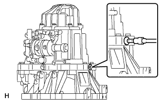
| 53. INSTALL BACK-UP LIGHT SWITCH ASSEMBLY |
Using SST, install the back-up light switch assembly onto the manual transmission case with a new gasket.
- SST
- 09817-16011
- Момент затяжки:
- 40 Н*м{410 кгс*см, 30 фунт-сила-футов}
Install the back-up light switch wire harness into the 2 clamps.
| 54. INSTALL SPEEDOMETER DRIVEN HOLE COVER SUB-ASSEMBLY |
Install a new O-ring to the speedometer driven hole cover sub-assembly.
Install the speedometer driven hole cover sub-assembly with the bolt to the transaxle case.
- Момент затяжки:
- 11 Н*м{115 кгс*см, 8 фунт-сила-футов}
| 55. INSTALL DRAIN (MTM) PLUG SUB-ASSEMBLY |
Install the drain (MTM) plug sub-assembly with a new gasket to the manual transmission case.
- Момент затяжки:
- 39 Н*м{400 кгс*см, 29 фунт-сила-футов}
| 56. INSTALL MANUAL TRANSMISSION FILLER PLUG |
Install the manual transmission filler plug with a new gasket to the manual transmission case cover.
- Момент затяжки:
- 39 Н*м{400 кгс*см, 29 фунт-сила-футов}