Система Посадки И Запуска Не Изменяется Режим Работы Источника Питания– Питание Не Включается (Ig). Corolla Auris
Двигатель. COROLLA, AURIS. ZZE150 ZRE151,152 NDE150
DESCRIPTION
WIRING DIAGRAM
INSPECTION PROCEDURE
INSPECT FUSE (AM2 NO. 2 AND IG2 NO. 2)
CHECK CONNECTORS
CHECK HARNESS AND CONNECTOR (MAIN BODY ECU - BATTERY)
CHECK HARNESS AND CONNECTOR (MAIN BODY ECU - BODY GROUND)
INSPECT ENGINE ROOM JUNCTION BLOCK (IG2 RELAY)
CHECK HARNESS AND CONNECTOR (ENGINE ROOM JUNCTION BLOCK - MAIN BODY ECU AND BODY GROUND)
INSPECT RELAY (IG1 RELAY)
CHECK HARNESS AND CONNECTOR (INSTRUMENT PANEL JUNCTION BLOCK - MAIN BODY ECU)
CHECK HARNESS AND CONNECTOR (INSTRUMENT PANEL JUNCTION BLOCK - BATTERY AND BODY GROUND)
СИСТЕМА ПОСАДКИ И ЗАПУСКА - Не изменяется режим работы источника питания– питание не включается (IG) |
DESCRIPTION
When the engine switch is pushed with the electrical key in the cabin, the main body ECU receives signals to switch the power source mode.- УКАЗАНИЕ:
- To allow use of the intelligent tester to inspect the push-button start function when the engine switch is off, repeat opening and closing any of the doors. Opening and closing a door establishes communication between the intelligent tester and the main body ECU. (Opening and closing a door can also be simulated by operating a door courtesy light switch.)
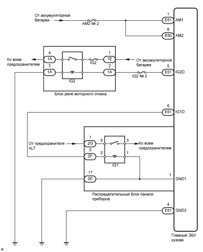
WIRING DIAGRAM
INSPECTION PROCEDURE
| 1.INSPECT FUSE (AM2 NO. 2 AND IG2 NO. 2) |
Remove the AM2 NO. 2 and IG2 NO. 2 fuse from the engine room junction block.
Measure the resistance of the fuse.
- Standard resistance:
- Below 1 Ω
Check that the connectors are securely connected and the terminals are not deformed or loose.
- OK:
- The connectors are securely connected and the terminals are not deformed or loose.
| | REPAIR OR REPLACE CONNECTORS |
|
|
| 3.CHECK HARNESS AND CONNECTOR (MAIN BODY ECU - BATTERY) |
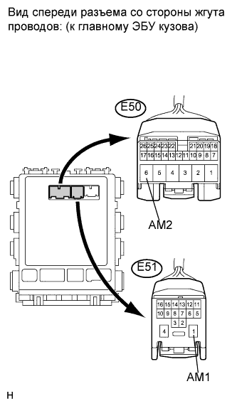
Disconnect the E50 and E51 ECU connectors.
Measure the voltage according to the value(s) in the table below.
- Standard voltage:
Tester Connection
| Condition
| Specified Condition
|
E51-1 (AM1) - Body ground
| Always
| 11 to 14 V
|
E50-6 (AM2) - Body ground
| Always
| 11 to 14 V
|
| | REPAIR OR REPLACE HARNESS OR CONNECTOR |
|
|
| 4.CHECK HARNESS AND CONNECTOR (MAIN BODY ECU - BODY GROUND) |
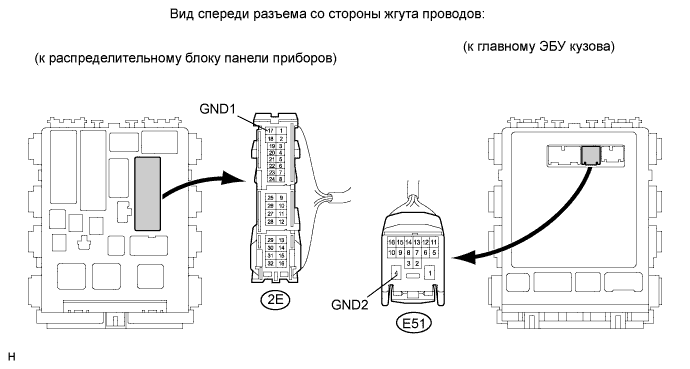
Disconnect the 2E junction block connector.
Measure the resistance according to the value(s) in the table below.
- Standard resistance:
Tester Connection
| Condition
| Specified Condition
|
2E-17 (GND1) - Body ground
| Always
| Below 1 Ω
|
E51-4 (GND2) - Body ground
|
| | REPAIR OR REPLACE HARNESS OR CONNECTOR |
|
|
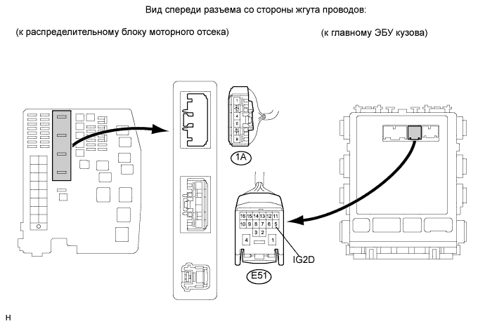
| 5.INSPECT ENGINE ROOM JUNCTION BLOCK (IG2 RELAY) |
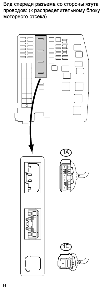
Disconnect the 1A engine room junction block connector.
Measure the voltage according to the value(s) in the table below.
- Standard voltage:
Tester Connection
| Condition
| Specified Condition
|
1A-4 - Body ground
| When battery voltage is not applied to terminals 1A-2 and 1A-3
| Below 1 V
|
1A-4 - Body ground
| When battery voltage is applied to terminals 1A-2 and 1A-3
| 11 to 14 V
|
| | REPLACE ENGINE ROOM JUNCTION BLOCK |
|
|
| 6.CHECK HARNESS AND CONNECTOR (ENGINE ROOM JUNCTION BLOCK - MAIN BODY ECU AND BODY GROUND) |
Measure the resistance according to the value(s) in the table below.
- Standard resistance:
Tester Connection
| Condition
| Specified Condition
|
1A-2 - E51-5 (IG2D)
| Always
| Below 1 Ω
|
1A-3 - Body ground
|
E51-5 (IG2D) - Body ground
| 10 kΩ or higher
|
| | REPAIR OR REPLACE HARNESS OR CONNECTOR |
|
|
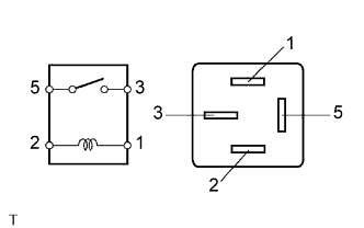
| 7.INSPECT RELAY (IG1 RELAY) |
Remove the IG1 relay from the instrument panel junction block.
Measure the resistance according to the value(s) in the table below.
- Standard resistance:
Tester Connection
| Condition
| Specified Condition
|
3 - 5
| When battery voltage is not applied to terminals 1 and 2
| 10 kΩ or higher
|
3 - 5
| When battery voltage is applied to terminals 1 and 2
| Below 1 Ω
|
| | REPLACE ENGINE ROOM JUNCTION BLOCK |
|
|
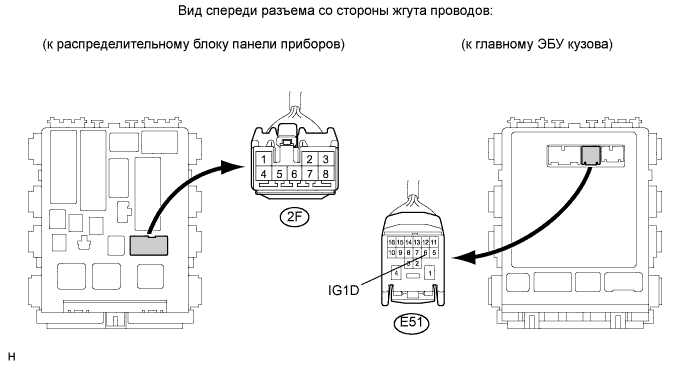
| 8.CHECK HARNESS AND CONNECTOR (INSTRUMENT PANEL JUNCTION BLOCK - MAIN BODY ECU) |
Disconnect the 2F junction block connector.
Measure the resistance according to the value(s) in the table below.
- Standard resistance:
Tester Connection
| Condition
| Specified Condition
|
2F-3 - E51-6 (IG1D)
| Always
| Below 1 Ω
|
E51-6 (IG1D) - Body ground
| 10 kΩ or higher
|
| | REPAIR OR REPLACE HARNESS OR CONNECTOR |
|
|
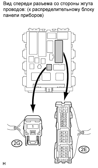
| 9.CHECK HARNESS AND CONNECTOR (INSTRUMENT PANEL JUNCTION BLOCK - BATTERY AND BODY GROUND) |
Disconnect the 2G junction block connector.
Measure the resistance according to the value(s) in the table below.
- Standard resistance:
Tester Connection
| Condition
| Specified Condition
|
2E-17 (GND1) - Body ground
| Always
| Below 1 Ω
|
Measure the voltage according to the value(s) in the table below.
- Standard voltage:
Tester Connection
| Condition
| Specified Condition
|
2G-1 - Body ground
| Always
| 11 to 14 V
|
| | REPAIR OR REPLACE HARNESS OR CONNECTOR |
|
|
| OK |
|
|
|
| REPLACE MAIN BODY ECU (INSTRUMENT PANEL JUNCTION BLOCK) |
|