Система Посадки И Запуска Не Изменяется Режим Работы Источника Питания– Питание Не Включается (Ig И Acc). Corolla Auris
Двигатель. COROLLA, AURIS. ZZE150 ZRE151,152 NDE150
DESCRIPTION
WIRING DIAGRAM
INSPECTION PROCEDURE
CHECK ENTRY FUNCTION DETECTION AREA
INSPECT FUSE (AM2 NO. 2)
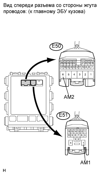
CHECK CONNECTORS
CHECK HARNESS AND CONNECTOR (MAIN BODY ECU - BATTERY)
CHECK HARNESS AND CONNECTOR (MAIN BODY ECU - BODY GROUND)
CHECK FOR DTCS
READ VALUE OF INTELLIGENT TESTER
INSPECT ENGINE SWITCH
CHECK HARNESS AND CONNECTOR (MAIN BODY ECU AND BODY GROUND - ENGINE SWITCH)
СИСТЕМА ПОСАДКИ И ЗАПУСКА - Не изменяется режим работы источника питания– питание не включается (IG и ACC) |
DESCRIPTION
When the engine switch is pushed with the electrical key in the cabin, the main body ECU receives signals to switch the power source mode.- УКАЗАНИЕ:
- To allow use of the intelligent tester to inspect the push-button start function when the engine switch is off, repeat opening and closing any of the doors. Opening and closing a door establishes communication between the intelligent tester and the main body ECU. (Opening and closing a door can also be simulated by operating a door courtesy light switch.)
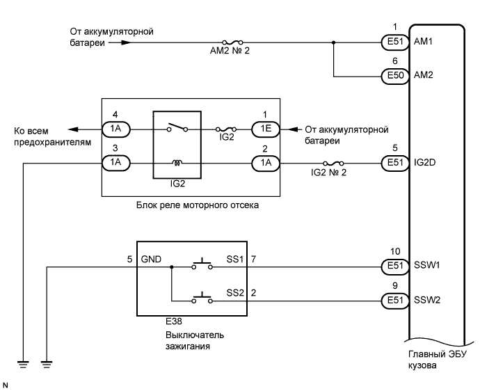
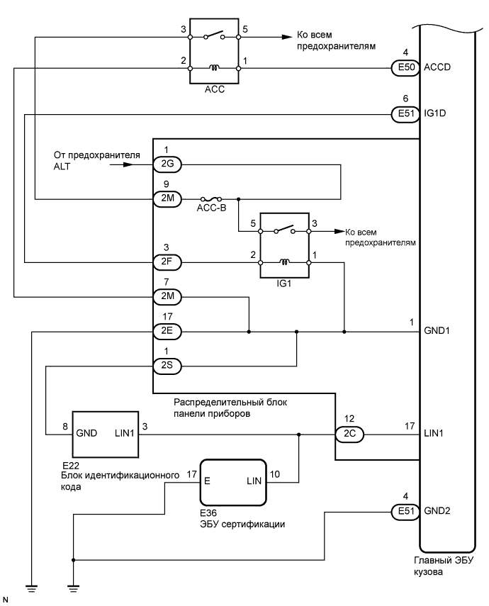
WIRING DIAGRAM
INSPECTION PROCEDURE
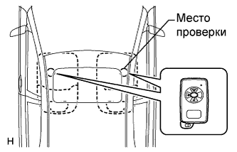
| 1.CHECK ENTRY FUNCTION DETECTION AREA |
Inspect entry detection area.
When the electrical key is in either of the 2 inspection points in the illustration, the clutch pedal is depressed, check that the engine switch indicator illuminates in green.
- OK:
- Engine switch illuminates in green.
- УКАЗАНИЕ:
- If the engine switch does not illuminate, perform troubleshooting according to PROBLEM SYMPTOMS TABLE (See page Нажмите здесь).
| 2.INSPECT FUSE (AM2 NO. 2) |
Remove the AM2 NO. 2 fuse from the engine room junction block.
Measure the resistance of the fuse.
- Standard resistance:
- Below 1 Ω
Check that the connectors are securely connected and the terminals are not deformed or loose.
- OK:
- The connectors are securely connected and the terminals are not deformed or loose.
| | REPAIR OR REPLACE CONNECTORS |
|
|
| 4.CHECK HARNESS AND CONNECTOR (MAIN BODY ECU - BATTERY) |
Disconnect the E50 and E51 ECU connectors.
Measure the voltage according to the value(s) in the table below.
- Standard voltage:
Tester Connection
| Condition
| Specified Condition
|
E51-1 (AM1) - Body ground
| Always
| 11 to 14 V
|
E50-6 (AM2) - Body ground
| Always
| 11 to 14 V
|
| | REPAIR OR REPLACE HARNESS OR CONNECTOR |
|
|
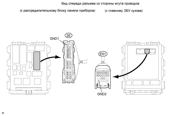
| 5.CHECK HARNESS AND CONNECTOR (MAIN BODY ECU - BODY GROUND) |
Disconnect the E51 ECU connector.
Disconnect the 2E junction block connector.
Measure the resistance according to the value(s) in the table below.
- Standard resistance:
Tester Connection
| Condition
| Specified Condition
|
2E-17 (GND1) - Body ground
| Always
| Below 1 Ω
|
E51-4 (GND2) - Body ground
| Always
| Below 1 Ω
|
| | REPAIR OR REPLACE HARNESS OR CONNECTOR |
|
|
Delete the DTCs (See page Нажмите здесь).
- УКАЗАНИЕ:
- After all the DTCs are cleared, check if the trouble occurs again 5 seconds after the engine switch is turned on (IG).
Check for DTCs again.
- OK:
- No DTC is output.
| 7.READ VALUE OF INTELLIGENT TESTER |
Connect the intelligent tester to the DLC3.
Turn the engine switch on (IG).
Check the DATA LIST for proper functioning of the start switches 1 and 2.
- УКАЗАНИЕ:
- When using the intelligent tester with the engine switch off, turn on and off any of the door courtesy light switches repeatedly at 1.5 second intervals or less until communication between the tester and vehicle starts.
Body:Tester Display
| Measurement Item/Range
| Normal Condition
| Diagnostic Note
|
St SW1
| Start Switch 1/ON or OFF
| ON: Engine switch is pushed
OFF: Engine switch is not pushed
| -
|
St SW2
| Start Switch 2/ON or OFF
| ON: Engine switch is pushed
OFF: Engine switch is not pushed
| -
|
- OK:
- ON (engine switch is pushed) and OFF (engine switch is not pushed) appear on the screen.
| OK |
|
|
|
| REPLACE MAIN BODY ECU (INSTRUMENT PANEL JUNCTION BLOCK) |
|
Remove the engine switch (for sedan: See page Нажмите здесь).
Remove the engine switch (for hatchback: See page Нажмите здесь).
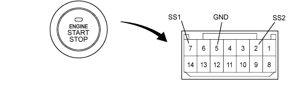
Measure the resistance of the switch.
- Standard resistance:
Tester Connection
| Switch Condition
| Specified Condition
|
7 (SS1) - 5 (GND)
| Pushed
| Below 1 Ω
|
2 (SS2) - 5 (GND)
| Pushed
| Below 1 Ω
|
7 (SS1) - 5 (GND)
| Not pushed
| 10 kΩ or higher
|
2 (SS2) - 5 (GND)
| Not pushed
| 10 kΩ or higher
|
Proceed to the next step based on the inspection result.
- Result:
Result
| Proceed to
|
OK
| A
|
NG (for sedan)
| B
|
NG (for hatchback)
| C
|
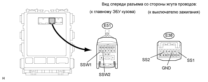
| 9.CHECK HARNESS AND CONNECTOR (MAIN BODY ECU AND BODY GROUND - ENGINE SWITCH) |
Disconnect the E51 ECU connector.
Disconnect the E38 switch connector.
Measure the resistance according to the value(s) in the table below.
- Standard resistance:
Tester Connection
| Condition
| Specified Condition
|
E38-7 (SS1) - E51-10 (SSW1)
| Always
| Below 1 Ω
|
E38-2 (SS2) - E51-9 (SSW2)
| Always
| Below 1 Ω
|
E38-5 (GND) - Body ground
| Always
| Below 1 Ω
|
E38-7 (SS1) or E51-10 (SSW1) - Body ground
| Always
| 10 kΩ or higher
|
E38-2 (SS2) or E51-9 (SSW2) - Body ground
| Always
| 10 kΩ or higher
|
| | REPAIR OR REPLACE HARNESS OR CONNECTOR |
|
|
| OK |
|
|
|
| REPLACE MAIN BODY ECU (INSTRUMENT PANEL JUNCTION BLOCK) |
|