Топливная Система Common Rail Снятие. Corolla Auris
Двигатель. COROLLA, AURIS. ZZE150 ZRE151,152 NDE150
DISCONNECT CABLE FROM NEGATIVE BATTERY TERMINAL
DRAIN ENGINE COOLANT
REMOVE NO. 1 ENGINE COVER
REMOVE AIR CLEANER CAP SUB-ASSEMBLY
SEPARATE OIL LEVEL DIPSTICK GUIDE
REMOVE EGR COOLER ASSEMBLY
REMOVE VACUUM REGULATING VALVE ASSEMBLY
REMOVE NO. 1 INJECTION PIPE CLAMP
REMOVE NO. 2 INJECTION PIPE CLAMP
REMOVE NO. 1 INJECTION PIPE SUB-ASSEMBLY
REMOVE NO. 2 INJECTION PIPE SUB-ASSEMBLY
REMOVE NO. 3 INJECTION PIPE SUB-ASSEMBLY
REMOVE NO. 4 INJECTION PIPE SUB-ASSEMBLY
REMOVE FUEL INLET PIPE SUB-ASSEMBLY
REMOVE COMMON RAIL ASSEMBLY
Топливная Система Common Rail -- Снятие |
| 1. DISCONNECT CABLE FROM NEGATIVE BATTERY TERMINAL |
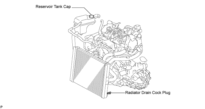
Loosen the radiator drain cock plug.
- УКАЗАНИЕ:
- Collect the coolant in a container and dispose of it according to the regulations in your area.
Remove the radiator reservoir cap.
- ПРЕДОСТЕРЕЖЕНИЕ:
- Do not remove the radiator reservoir cap while the engine and radiator are still hot.
- Pressurized, hot engine coolant and steam may be released and cause serious burns.
Loosen the cylinder block drain cock plug.
- УКАЗАНИЕ:
- The plug is on the backside of the generator on the exhaust manifold side.
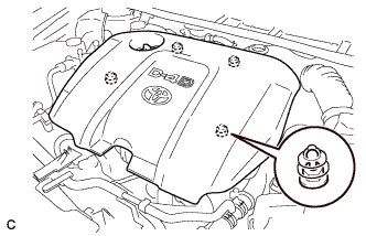
| 3. REMOVE NO. 1 ENGINE COVER |
Disengage the 4 pins and remove No. 1 engine cover sub-assembly.
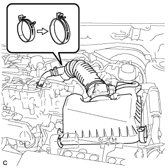
| 4. REMOVE AIR CLEANER CAP SUB-ASSEMBLY |
Disconnect the mass air flow meter connector.
Disconnect the No. 2 ventilation hose.
Disconnect the 2 clamps and band, and remove the air cleaner cap sub-assembly.
| 5. SEPARATE OIL LEVEL DIPSTICK GUIDE |
Remove the bolt and oil level gauge guide.
| 6. REMOVE EGR COOLER ASSEMBLY |
Disconnect the 2 water by-pass hoses.
Remove the bolt and 4 nuts, then remove the EGR cooler assembly.
Remove the 2 gaskets.
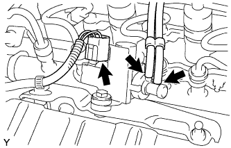
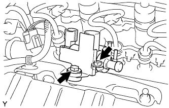
| 7. REMOVE VACUUM REGULATING VALVE ASSEMBLY |
Disconnect the vacuum regulating valve connector.
Disconnect the 2 vacuum hoses from the vacuum regulating valve.
Remove the 2 bolts and vacuum regulating valve.
| 8. REMOVE NO. 1 INJECTION PIPE CLAMP |
| 9. REMOVE NO. 2 INJECTION PIPE CLAMP |
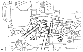
| 10. REMOVE NO. 1 INJECTION PIPE SUB-ASSEMBLY |
Using a wrench (13 mm), hold the injector steadily, and using SST, remove the injection pipe from the injector side.
- SST
- 09023-38401
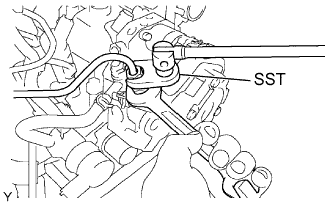
Using SST, remove the injection pipe from the common rail side.
- SST
- 09023-38401
After removing the injection pipe, cover the common rail with vinyl tape and cover the injector inlet with a plastic bag in order to prevent dust and foreign matter from entering.
| 11. REMOVE NO. 2 INJECTION PIPE SUB-ASSEMBLY |
- SST
- 09023-38401
- УКАЗАНИЕ:
- Perform the same procedure as for the No. 1 injection pipe.
| 12. REMOVE NO. 3 INJECTION PIPE SUB-ASSEMBLY |
- SST
- 09023-38401
- УКАЗАНИЕ:
- Perform the same procedure as for the No. 1 injection pipe.
| 13. REMOVE NO. 4 INJECTION PIPE SUB-ASSEMBLY |
- SST
- 09023-38401
- УКАЗАНИЕ:
- Perform the same procedure as for the No. 1 injection pipe.
| 14. REMOVE FUEL INLET PIPE SUB-ASSEMBLY |
Using a wrench (17 mm), hold the supply pump steadily, and using SST, remove the fuel inlet pipe from the supply pump side.
- SST
- 09023-38401
Using SST, remove the fuel inlet pipe from the common rail side.
- SST
- 09023-38401
After removing the fuel inlet pipe, cover the common rail with vinyl tape and cover the injector inlet with a plastic bag in order to prevent dust and foreign matter from entering.
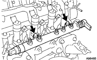
| 15. REMOVE COMMON RAIL ASSEMBLY |
- SST
- 09023-38401
Disconnect the 2 connectors.
Disconnect the fuel hose.
Remove the 2 bolts and common rail.
- ПРИМЕЧАНИЕ:
- Do not remove the fuel pressure sensor or fuel pressure regulator.