Нагнетающий Топливный Насос -- Установка |
| 1. INSTALL SUPPLY PUMP ASSEMBLY |
Install a new O-ring to the supply pump assembly.
Install the supply pump drive coupling.
- ПРИМЕЧАНИЕ:
- When reusing the coupling, install the coupling in the same orientation (top/bottom, front/back) as when it was removed.
- УКАЗАНИЕ:
- Line up the coupling with the groove in the camshaft end.
Install the supply pump assembly and the 2 bolts.
- Момент затяжки:
- 21 Н*м{214 кгс*см, 15 фунт-сила-футов}
- ПРИМЕЧАНИЕ:
- Apply the engine oil to the O-ring of the supply pump assembly.
- УКАЗАНИЕ:
- Remember the orientation of the supply pump drive coupling when removing the supply pump from the cylinder head.
Connect the suction control valve assembly.
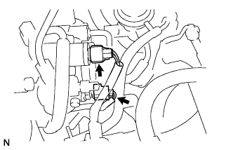 |
Connect the fuel temperature sensor connector.
| 2. INSTALL FUEL INLET PIPE SUB-ASSEMBLY |
- ПРИМЕЧАНИЕ:
- If the injection or supply pump is replaced, the fuel inlet pipe must also be replaced.
Temporarily install the fuel inlet pipe with the 2 clamps and nut.
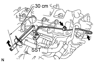 |
Using SST, first tighten the nut at the common rail end of the fuel inlet pipe.
- SST
- 09023-38401
- Момент затяжки:
- without SST:
- 30 Н*м{306 кгс*см, 22 фунт-сила-футов}
- with SST:
- 27 Н*м{275 кгс*см, 20 фунт-сила-футов}
- УКАЗАНИЕ:
- Use of proper SST is necessary to ensure that the correct torque is applied to the injection pipe nut.
- Use a torque wrench with a fulcrum length of 30 cm (11.81 in.).
- Make sure that the pipe is not deformed or twisted during installation.
If the pipe is deformed or twisted, or if it cannot be installed properly, replace the pipe with a new one.
Using SST, tighten the nut at the supply pump end of the fuel inlet pipe.
- SST
- 09023-38401
- Момент затяжки:
- without SST:
- 34 Н*м{347 кгс*см, 25 фунт-сила-футов}
- with SST:
- 31 Н*м{316 кгс*см, 23 фунт-сила-футов}
- УКАЗАНИЕ:
- Use of proper SST is necessary to ensure that the correct torque is applied to the injection pipe nut.
- Use a torque wrench with a fulcrum length of 30 cm (11.81 in.).
- Make sure that the pipe is not deformed or twisted during installation.
If the pipe is deformed or twisted, or if it cannot be installed properly, replace the pipe with a new one.
Tighten the fuel inlet pipe clamp nut.
- Момент затяжки:
- 5.0 Н*м{51 кгс*см, 44 фунт-сила-дюймов}
| 3. INSTALL NO. 1 FUEL HOSE |
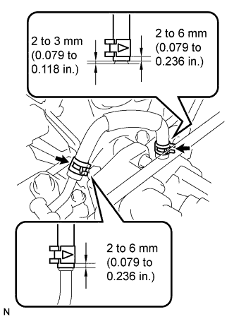
Using pliers, slide the 2 clips to install the No. 1 fuel hose.
 |
| 4. INSTALL FUEL TUBE SUB-ASSEMBLY (for DPF) |
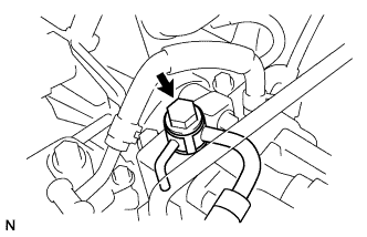
Install the fuel tube sub-assembly and a new gasket with the union bolt.
- Момент затяжки:
- 23 Н*м{235 кгс*см, 17 фунт-сила-футов}
 |
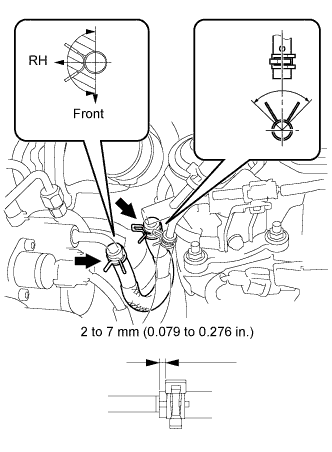
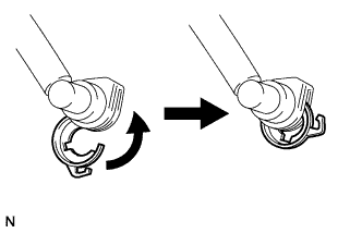
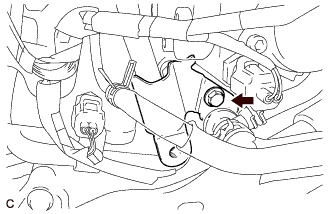
Turn the retainer in the direction indicated by the arrow until the retainer stops.
 |
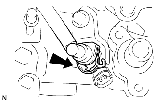
Insert the fuel tube connector into the injector.
 |
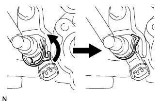
Turn the retainer in the direction indicated by the arrow until it makes a "click" sound.
- ПРИМЕЧАНИЕ:
- If the fuel tube connector is not inserted to the correct position of the injector, the retainer cannot be turned further in the direction of the arrow.
 |
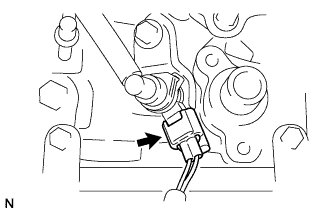
Connect the exhaust fuel addition injector connector.
 |
| 5. INSTALL FUEL HOSE PROTECTOR (for DPF) |
Install the fuel hose protector with the bolt.
- Момент затяжки:
- 40 Н*м{408 кгс*см, 30 фунт-сила-футов}
 |
| 6. INSTALL NO. 3 FUEL HOSE |
Using pliers, slide the 2 clips to install the No. 3 fuel hose.
 |
| 7. INSTALL AIR CLEANER CASE |
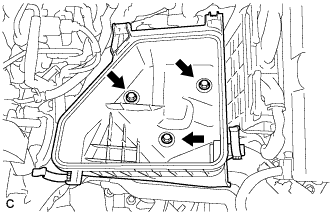
Install the 3 bolts and air cleaner case.
- Момент затяжки:
- 7.0 Н*м{71 кгс*см, 62 фунт-сила-дюймов}
 |
| 8. INSTALL AIR CLEANER CAP SUB-ASSEMBLY |
Install the air cleaner filter element.
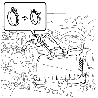
Install the air cleaner cap sub-assembly, and connect the 2 clamps and band.
 |
Connect the No. 2 ventilation hose.
Connect the mass air flow meter connector.
| 9. CONNECT CABLE TO NEGATIVE BATTERY TERMINAL |
| 10. INSPECT FOR FUEL LEAK |
- УКАЗАНИЕ:
- Using the intelligent tester to perform Active Tests allow relays, VSVs, actuators and other items to be operated without removing any parts. This non-intrusive functional inspection can be very useful because intermittent operation may be discovered before parts or wiring is disturbed. Performing Active Tests early in troubleshooting is one way to save diagnostic time. Data List information can be displayed while performing Active Tests.
PERFORM ACTIVE TEST
Connect the intelligent tester to the DLC3.
Turn the ignition switch on (IG).
Turn the intelligent tester on.
Enter the following menus: Powertrain / Engine / Active Test.
Perform the Active Test.
Tester Display Test Part Control Range Diagnostic Notes Test the Fuel Leak Pressurizes common rail internal fuel pressure, and checks for fuel leaks Stop/Start - Fuel pressure inside common rail pressurized to specified value and engine speed increased to 2000 rpm when ON is selected
- Above conditions preserved while test is ON
- Fuel pressure inside common rail pressurized to specified value and engine speed increased to 2000 rpm when ON is selected
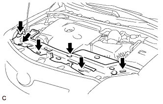
| 11. INSTALL UPPER RADIATOR AIR DEFLECTOR |
Install the 6 clips and upper radiator air deflector.
 |
| 12. INSTALL NO. 1 ENGINE COVER |
Attach the 4 clips to install the engine cover.
 |
| 13. INITIALIZE THE LEARNING VALUE OF THE SUPPLY PUMP ASSEMBLY |
Perform initialization procedure (See page Нажмите здесь).