INSTALL WINDSHIELD WIPER MOTOR AND LINK ASSEMBLY (for Sedan)
INSTALL WINDSHIELD WIPER MOTOR AND LINK ASSEMBLY (for Hatchback)
INSTALL FRONT WIPER ARM AND BLADE ASSEMBLY RH (for Hatchback)
INSTALL FRONT WIPER ARM AND BLADE ASSEMBLY LH (for Hatchback)
Топливная Форсунка -- Установка |
| 1. INSTALL INJECTOR ASSEMBLY |
Install the new nozzle seat to the cylinder head.
Install new O-rings to each injector.
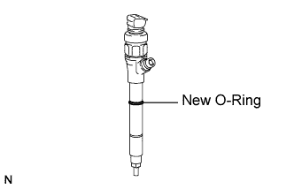 |
Apply a light coat of engine oil to the O-rings on each injector.
Install the injectors to the cylinder head.
- ПРИМЕЧАНИЕ:
- Fit the injectors to the nozzle seats.
Install the nozzle holder clamp and washer as shown in the illustration.
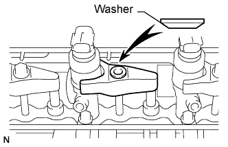 |
Install the nozzle holder clamp bolts by hand.
- ПРИМЕЧАНИЕ:
- Pay attention to the mounting direction (beveled edge) of the washer.
- When temporarily attaching the nozzle holder clamp and the mounting bolt, be careful not to position them at an angle.
- УКАЗАНИЕ:
- Apply a light coat of engine oil to the threads of the nozzle holder clamp bolts.
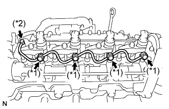
Temporarily install the No. 1, No. 2, No. 3 and No. 4 injection pipes.
Temporarily install 5 new gaskets, the leakage pipe, bolt and 5 union bolts.
Tighten the 4 nozzle holder clamp bolts.
- Момент затяжки:
- 25 Н*м{255 кгс*см, 18 фунт-сила-футов}
Remove the 4 injection pipes.
| 2. INSTALL NOZZLE LEAKAGE PIPE ASSEMBLY |
Tighten the 5 union bolts.
- Момент затяжки:
- (*1):
- 18 Н*м{183 кгс*см, 13 фунт-сила-футов}
- (*2):
- 22 Н*м{224 кгс*см, 16 фунт-сила-футов}
 |
Check that there are no leaks from the nozzle leakage pipe connection.
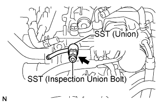
Install SST and gasket.
- SST
- 09280-00010
09268-45014
(90405-06167)
- Момент затяжки:
- 21 Н*м{214 кгс*см, 15 фунт-сила-футов}
Apply a light coat of soapy water (any fluid to detect fuel leakage) to the No. 2 nozzle leakage pipe connection.
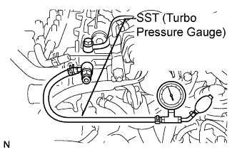
Using SST (turbocharger pressure gauge), attach SST (turbocharger pressure gauge) to the fuel return side of SST (union), and maintain 100 kPa (1.0 kgf/cm2, 14.5 psi) of pressure for 60 seconds to check that there are no bubbles from the pipe connection.
- SST
- 09992-00242
After checking for fuel leaks, wipe off soapy water from the pipe connection.
Remove SST and gasket.
| 3. INSTALL CYLINDER HEAD COVER SUB-ASSEMBLY |
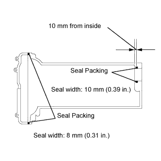
Clean the contact surfaces of the cylinder head cover, cylinder head assembly and timing chain cover assembly.
Apply seal packing to the contact portions between the cylinder head and the chain cover, and between the cylinder head and the cam cap as shown in the illustration.
- Seal Packing:
- Part No. 08826-00080 or equivalent
- ПРИМЕЧАНИЕ:
- Remove any oil from the contact surface.
- Install the cylinder head cover within 3 minutes after applying seal packing.
- Do not apply engine oil for at least 2 hours after installing the cylinder head cover.
 |
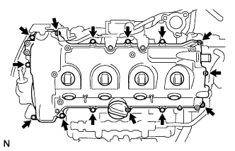
Fit a new cylinder head cover gasket into the gasket groove on the cover.
Install the cylinder head cover with the 12 bolts, 2 nuts and 2 washers.
Uniformly tighten the bolts and nuts in several passes.- Момент затяжки:
- 11 Н*м{112 кгс*см, 8 фунт-сила-футов}
 |
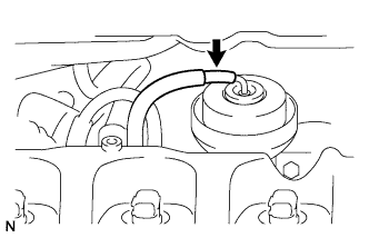
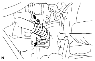
Connect the vacuum hose to the turbocharger actuator.
 |
Align the connector with the pipe, then push in the connector to the pipe until it makes a "click" sound to connect the vacuum hose to the vacuum pump (*1).
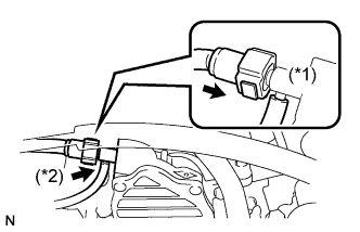 |
Connect the vacuum hose to the vacuum pump (*2).
Connect the power steering hose to the vacuum pump.
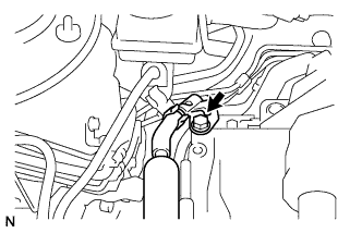 |
Install the bolt.
| 4. INSTALL NOZZLE HOLDER SEAL |
Install the 4 nozzle holder seals.
- ПРИМЕЧАНИЕ:
- Apply a light coat of silicone oil to the nozzle holder seal side.
| 5. INSTALL NO. 2 NOZZLE LEAKAGE PIPE |
Install the No. 2 nozzle leakage pipe, gasket and 2 bolts.
- Момент затяжки:
- 32 Н*м{321 кгс*см, 23 фунт-сила-футов}
 |
Using pliers, grip the claws of the 3 clips and slide the 3 clips to connect the 3 fuel hoses.
| 6. INSTALL NO. 1 INJECTION PIPE SUB-ASSEMBLY |
- ПРИМЕЧАНИЕ:
- If an injector is replaced, the injection pipes must also be replaced.
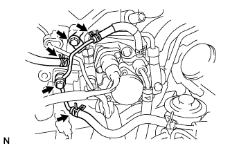
Temporarily install the 4 injection pipes.
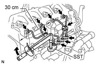 |
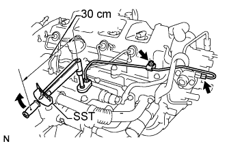
Using SST, tighten the nut at the common rail end of the injection pipe.
- SST
- 09023-38401
- Момент затяжки:
- without SST:
- 30 Н*м{306 кгс*см, 22 фунт-сила-футов}
- with SST:
- 27 Н*м{275 кгс*см, 20 фунт-сила-футов}
- УКАЗАНИЕ:
- Use of proper SST is necessary to ensure that the correct torque is applied to the injection pipe nut.
- Use a torque wrench with a fulcrum length of 30 cm (11.81 in.).
- Make sure that the pipe is not deformed or twisted during installation.
If the pipe is deformed or twisted, or if it cannot be installed properly, replace the pipe with a new one.
Using SST, tighten the nut at the injector end of the injection pipe.
- SST
- 09023-12701
- Момент затяжки:
- without SST:
- 34 Н*м{347 кгс*см, 25 фунт-сила-футов}
- with SST:
- 31 Н*м{316 кгс*см, 23 фунт-сила-футов}
- УКАЗАНИЕ:
- Use of proper SST is necessary to ensure that the correct torque is applied to the injection pipe nut.
- Use a torque wrench with a fulcrum length of 30 cm (11.81 in.).
- Make sure that the pipe is not deformed or twisted during installation.
If the pipe is deformed or twisted, or if it cannot be installed properly, replace the pipe with a new one.
| 7. INSTALL NO. 2 INJECTION PIPE SUB-ASSEMBLY |
- УКАЗАНИЕ:
- Perform the same procedure as for the No. 1 injection pipe.
| 8. INSTALL NO. 3 INJECTION PIPE SUB-ASSEMBLY |
- УКАЗАНИЕ:
- Perform the same procedure as for the No. 1 injection pipe.
| 9. INSTALL NO. 4 INJECTION PIPE SUB-ASSEMBLY |
- УКАЗАНИЕ:
- Perform the same procedure as for the No. 1 injection pipe.
Install the 4 injection pipe clamps with the 2 bolts.
- Момент затяжки:
- 5.0 Н*м{51 кгс*см, 44 фунт-сила-дюймов}
| 10. INSTALL FUEL INLET PIPE SUB-ASSEMBLY |
Temporarily install the fuel inlet pipe with the 2 clamps and nut.
 |
Using SST, tighten the nut at the common rail end of the fuel inlet pipe.
- SST
- 09023-38401
- Момент затяжки:
- without SST:
- 30 Н*м{306 кгс*см, 22 фунт-сила-футов}
- with SST:
- 27 Н*м{275 кгс*см, 20 фунт-сила-футов}
- УКАЗАНИЕ:
- Use of proper SST is necessary to ensure that the correct torque is applied to the injection pipe nut.
- Use a torque wrench with a fulcrum length of 30 cm (11.81 in.).
- Make sure that the pipe is not deformed or twisted during installation.
If the pipe is deformed or twisted, or if it cannot be installed properly, replace the pipe with a new one.
Using SST, tighten the nut at the injection or supply pump end of the fuel inlet pipe.
- SST
- 09023-38401
- Момент затяжки:
- without SST:
- 30 Н*м{306 кгс*см, 22 фунт-сила-футов}
- with SST:
- 27 Н*м{275 кгс*см, 20 фунт-сила-футов}
- УКАЗАНИЕ:
- Use of proper SST is necessary to ensure that the correct torque is applied to the injection pipe nut.
- Use a torque wrench with a fulcrum length of 30 cm (11.81 in.).
- Make sure that the pipe is not deformed or twisted during installation.
If the pipe is deformed or twisted, or if it cannot be installed properly, replace the pipe with a new one.
Tighten the fuel inlet pipe clamp nut.
- Момент затяжки:
- 5.0 Н*м{51 кгс*см, 44 фунт-сила-дюймов}
| 11. INSTALL AIR CLEANER CAP SUB-ASSEMBLY |
Install the air cleaner filter element.
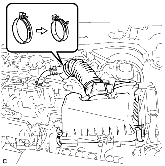
Install the air cleaner cap sub-assembly, and connect the 2 clamps and band.
 |
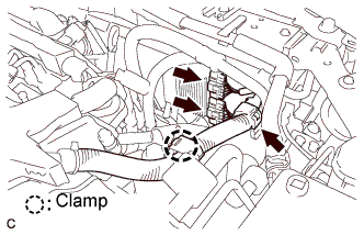
Connect the No. 2 ventilation hose.
Connect the mass air flow meter connector.
| 12. CONNECT ENGINE WIRE |
Connect the vacuum regulating valve connector.
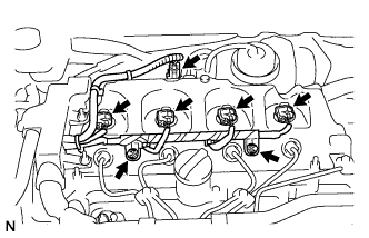 |
Connect the injector connectors.
Connect the engine wire to the cylinder head cover.
Install the 2 nuts.
Connect the 2 injector driver connectors and install the 2 clamps.
 |
Connect the generator wire.
 |
Install the nut.
Connect the generator connector.
Connect the cam position sensor connector.
 |
Connect the crankshaft position sensor connector.
Connect the engine wire to the cylinder head cover.
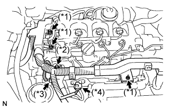 |
Connect the engine wire to the engine cover bracket.
Install the 3 nuts (*1).
Connect the glow plug harness.
Install the nut and grommet (*2).
- Момент затяжки:
- 2.2 Н*м{22 кгс*см, 19 фунт-сила-дюймов}
Connect the fuel pressure sensor connector (*3).
Connect the turbo pressure sensor connector(*4).
| 13. CONNECT CABLE TO NEGATIVE BATTERY TERMINAL |
| 14. REGISTRATION OF INJECTOR COMPENSATION CODE |
- УКАЗАНИЕ:
- Each injector assembly has a characteristic fuel injecting behavior (See page Нажмите здесь).
| 15. INSPECT FOR FUEL LEAK |
- УКАЗАНИЕ:
- Using the intelligent tester to perform Active Tests allow relays, VSVs, actuators and other items to be operated without removing any parts. This non-intrusive functional inspection can be very useful because intermittent operation may be discovered before parts or wiring is disturbed. Performing Active Tests early in troubleshooting is one way to save diagnostic time. Data List information can be displayed while performing Active Tests.
PERFORM ACTIVE TEST
Connect the intelligent tester to the DLC3.
Turn the ignition switch on (IG).
Turn the intelligent tester on.
Enter the following menus: Powertrain / Engine / Active Test.
Perform the Active Test.
Tester Display Test Part Control Range Diagnostic Notes Test the Fuel Leak Pressurizes common rail internal fuel pressure, and checks for fuel leaks Stop/Start - Fuel pressure inside common rail pressurized to specified value and engine speed increased to 2000 rpm when ON is selected
- Above conditions preserved while test is ON
- Fuel pressure inside common rail pressurized to specified value and engine speed increased to 2000 rpm when ON is selected
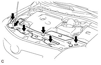
| 16. INSTALL NO. 1 ENGINE COVER |
Attach the 4 clips to install the engine cover.
 |
| 17. INSTALL UPPER RADIATOR AIR DEFLECTOR |
Install the 6 clips and upper radiator air deflector.
 |
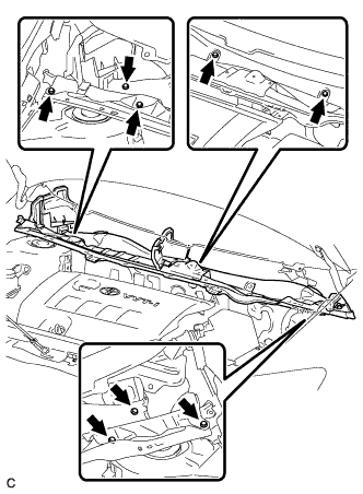
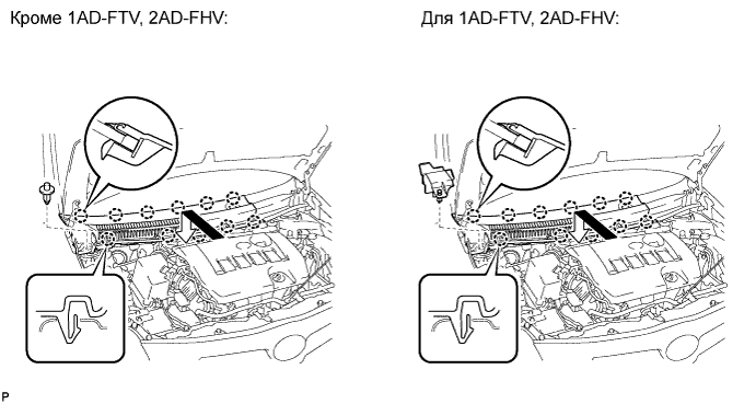
| 18. INSTALL COWL TOP PANEL OUTER (for Sedan) |
Установите наружную верхнюю панель кожуха и закрепите ее 10 болтами.
- Момент затяжки:
- 8,8 Н*м{90 кгс*см, 78 фунт-сила-дюймов}
 |
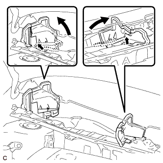
Отогните правую водозащитную пластину, как показано на рисунке, и введите в зацепление зажим.
 |
| 19. INSTALL COWL TOP PANEL OUTER (for Hatchback) |
Установите наружную верхнюю панель кожуха и закрепите ее 8 болтами.
- Момент затяжки:
- 8,8 Н*м{90 кгс*см, 78 фунт-сила-дюймов}
 |
Отогните правую водозащитную пластину и брызгозащитное уплотнение воздуховода отопителя № 1 и отсоедините все зажимы, как показано на рисунке.
 |
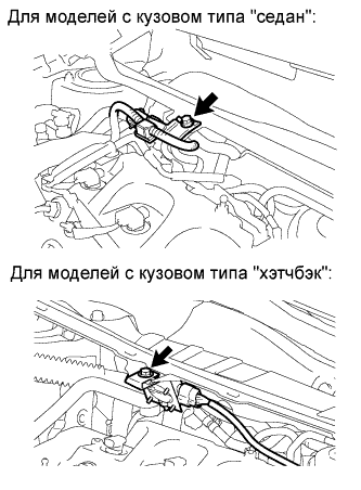
| 20. INSTALL DIFFERENTIAL PRESSURE SENSOR ASSEMBLY (for DPF) |
Установите дифференциальный датчик давления в сборе на наружную верхнюю панель кожуха и закрепите его болтом.
- Момент затяжки:
- 5,5 Н*м{56 кгс*см, 49 фунт-сила-дюймов}
 |
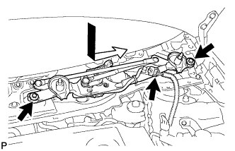
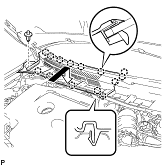
| 21. INSTALL WINDSHIELD WIPER MOTOR AND LINK ASSEMBLY (for Sedan) |
Установите электродвигатель стеклоочистителя ветрового стекла с тягой в сборе и закрепите его 2 болтами.
- Момент затяжки:
- 5,5 Н*м{56 кгс*см, 49 фунт-сила-дюймов}
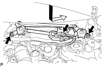 |
Подсоедините разъем.
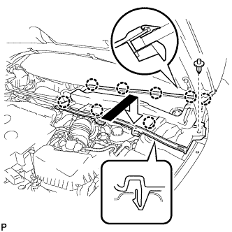
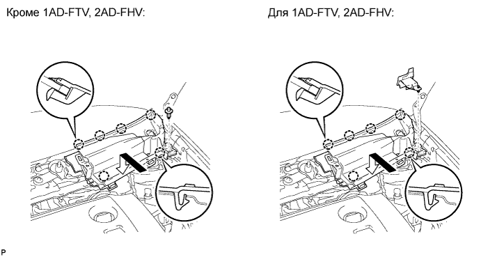
| 22. INSTALL WINDSHIELD WIPER MOTOR AND LINK ASSEMBLY (for Hatchback) |
Установите электродвигатель стеклоочистителя ветрового стекла с тягой в сборе и закрепите его 2 болтами.
- Момент затяжки:
- 5,5 Н*м{56 кгс*см, 49 фунт-сила-дюймов}
 |
Подсоедините разъем.
| 23. INSTALL COWL TOP VENTILATOR LOUVER LH (for Sedan) |
Введите в зацепление фиксатор и 8 захватов и установите левую вентиляционную решетку в верхней части кожуха.
 |
| 24. INSTALL COWL TOP VENTILATOR LOUVER LH (for Hatchback) |
Введите в зацепление фиксатор и 6 захватов и установите левую вентиляционную решетку в верхней части кожуха.
| 25. INSTALL COWL TOP VENTILATOR LOUVER RH (for Sedan) |
Введите в зацепление фиксатор и 14 захватов и установите правую вентиляционную решетку в верхней части кожуха.
 |
| 26. INSTALL COWL TOP VENTILATOR LOUVER RH (for Hatchback) |
Введите в зацепление фиксатор и 11 захватов и установите правую вентиляционную решетку в верхней части кожуха.
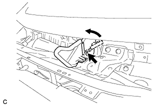
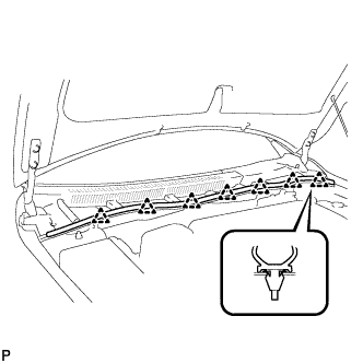
| 27. INSTALL HOOD TO COWL TOP SEAL |
Освободите 7 фиксаторов и отсоедините верхнее уплотнение между капотом и кожухом.
 |
| 28. INSTALL FRONT WIPER ARM AND BLADE ASSEMBLY RH (for Sedan) |
Приведите в действие стеклоочиститель и остановите электродвигатель стеклоочистителя ветрового стекла в положении автоматического ограничения хода.
Очистите зубчатую часть рычага стеклоочистителя.
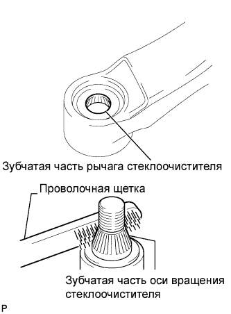 |
При повторной установке:
Почистите зубчатую часть оси вращения стеклоочистителя проволочной щеткой.
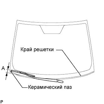
Установите правый рычаг переднего стеклоочистителя со щеткой в сборе, как показано на рисунке, и закрепите их гайкой.
- Момент затяжки:
- 26 Н*м{265 кгс*см, 19 фунт-сила-футов}
- УКАЗАНИЕ:
- Удерживайте шарнир рычага рукой, чтобы затянуть гайку.
Участок Измерение А 17,5–32,5 мм (0,69–1,28 дюйма)
 |
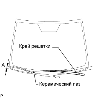
| 29. INSTALL FRONT WIPER ARM AND BLADE ASSEMBLY RH (for Hatchback) |
Приведите в действие стеклоочиститель и остановите электродвигатель стеклоочистителя ветрового стекла в положении автоматического ограничения хода.
Очистите зубчатую часть рычага стеклоочистителя.
|
При повторной установке:
Почистите зубчатую часть оси вращения стеклоочистителя проволочной щеткой.
Установите правый рычаг переднего стеклоочистителя со щеткой в сборе, как показано на рисунке, и закрепите их гайкой.
- Момент затяжки:
- 26 Н*м{265 кгс*см, 19 фунт-сила-футов}
- УКАЗАНИЕ:
- Удерживайте шарнир рычага рукой, чтобы затянуть гайку.
Участок Измерение А 17,5–32,5 мм (0,39–1,57 дюйма)
 |
| 30. INSTALL FRONT WIPER ARM AND BLADE ASSEMBLY LH (for Sedan) |
Приведите в действие стеклоочиститель и остановите электродвигатель стеклоочистителя ветрового стекла в положении автоматического ограничения хода.
Очистите зубчатую часть рычага стеклоочистителя.
|
При повторной установке:
Почистите зубчатую часть оси вращения стеклоочистителя проволочной щеткой.
Установите левый рычаг переднего стеклоочистителя со щеткой в сборе, как показано на рисунке, и закрепите их гайкой.
- Момент затяжки:
- 26 Н*м{265 кгс*см, 19 фунт-сила-футов}
- УКАЗАНИЕ:
- Удерживайте шарнир рычага рукой, чтобы затянуть гайку.
Участок Измерение А 22,5–37,5 мм (0,89–1,48 дюйма)
 |
Приведите в действие передние стеклоочистители, одновременно распыляя омывающую жидкость на ветровое стекло. Убедитесь, что передние стеклоочистители работают надлежащим образом и не задевают кузов автомобиля.
| 31. INSTALL FRONT WIPER ARM AND BLADE ASSEMBLY LH (for Hatchback) |
Приведите в действие стеклоочиститель и остановите электродвигатель стеклоочистителя ветрового стекла в положении автоматического ограничения хода.
Очистите зубчатую часть рычага стеклоочистителя.
|
При повторной установке:
Почистите зубчатую часть оси вращения стеклоочистителя проволочной щеткой.
Установите левый рычаг переднего стеклоочистителя со щеткой в сборе, как показано на рисунке, и закрепите их гайкой.
- Момент затяжки:
- 26 Н*м{265 кгс*см, 19 фунт-сила-футов}
- УКАЗАНИЕ:
- Удерживайте шарнир рычага рукой, чтобы затянуть гайку.
Участок Измерение А 25,5–40,5 мм (0,71–1,89 дюйма)
 |
Приведите в действие передние стеклоочистители, одновременно распыляя омывающую жидкость на ветровое стекло. Убедитесь, что передние стеклоочистители работают надлежащим образом и не задевают кузов автомобиля.
| 32. INSTALL FRONT WIPER ARM HEAD CAP |