Прокладка Головки Блока Цилиндров -- Установка |
| 1. INSTALL CYLINDER HEAD GASKET |
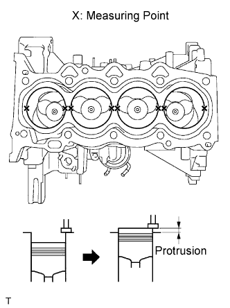
Inspect the protrusion height of the piston heads.
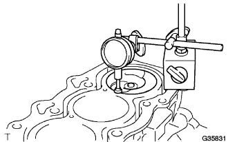
Place a dial indicator on the cylinder block as shown in the illustration.
- ПРИМЕЧАНИЕ:
- Make sure that the dial indicator is at right angles to the cylinder block top surface.
Measure the protrusion height of the piston head of each cylinder at 2 places as shown in the illustration.
 |
Select a new cylinder head gasket.
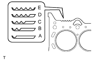
Select the highest protrusion height among the 8 measurement records. Use it to select a new cylinder head gasket.
- Piston protrusion:
Piston protrusion mm (in.) Gasket cutout Gasket size 0.375 to 0.425
(0.015 to 0.018)1 A 0.425 to 0.475
(0.018 to 0.019)2 B 0.475 to 0.525
(0.019 to 0.021)3 C 0.525 to 0.575
(0.021 to 0.023)4 D 0.575 to 0.625
(0.023 to 0.025)5 E
 |
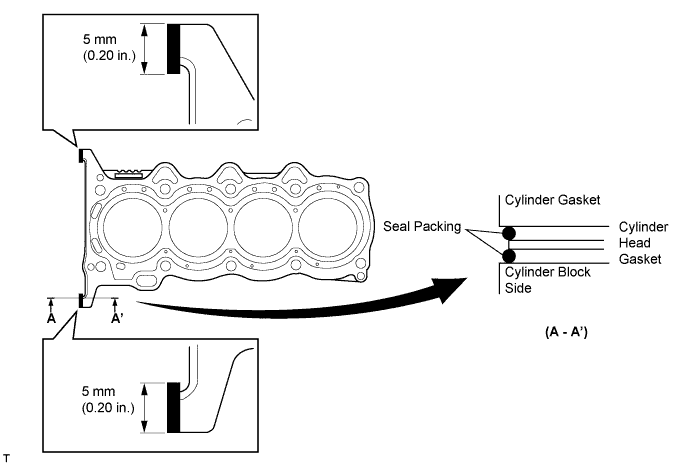
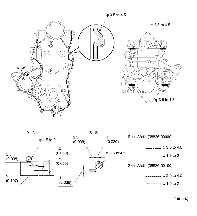
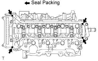
Install the cylinder head gasket.
Apply seal packing (Diameter 3.5 to 4.5 mm (0.138 to 0.177 in.)) to the cylinder block side shown in the illustration.
- Seal packing:
- Toyota Genuine Seal Packing Black, Three Bond 1207B or equivalent
- ПРИМЕЧАНИЕ:
- Remove any oil from the contact surface.
Place a new cylinder head gasket on the cylinder block with the Lot No. stamp facing upward.
Apply seal packing (Diameter 3.5 to 4.5 mm (0.138 to 0.177 in.)) to the top surface of the cylinder head again as shown in the illustration.
- Seal packing:
- Toyota Genuine Seal Packing Black, Three Bond 1207B or equivalent
Install the cylinder head onto the cylinder block.
- ПРИМЕЧАНИЕ:
- Remove any oil from the contact surface.
- Install the cylinder head within 3 minutes, and tighten the bolts within 15 minutes of applying the seal packing.
| 2. INSTALL CYLINDER HEAD SUB-ASSEMBLY |
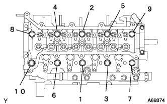 |
- SST
- 09817-33190
- УКАЗАНИЕ:
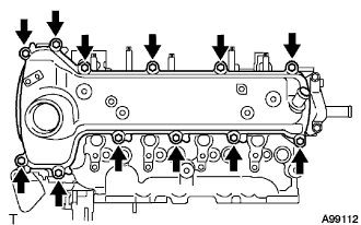
- The cylinder head bolts are tightened in 3 steps.
Apply a light coat of engine oil to the threads of the cylinder head bolts.
Using several passes, uniformly install and tighten the 10 cylinder head bolts and plate washers in the sequence shown in the illustration. (*1)
- Момент затяжки:
- 68 Н*м{693 кгс*см, 50 фунт-сила-футов}
Mark the front of the cylinder head bolts with paint.
 |
Using the same sequence as step (*1), tighten the cylinder head bolts by 90° as shown in the illustration.
Using the same sequence as step (*1), tighten the cylinder head bolts by an additional 90° as shown in the illustration.
Check that each paint mark is now 180° from the front.
Connect each connector and wire harness to the cylinder head.
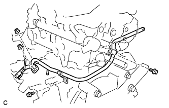
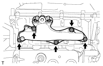
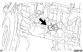
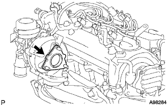
| 3. INSTALL NO. 1 WATER BY-PASS PIPE |
Install a new gasket, then install No. 1 water by-pass pipe with the 2 bolts and 2 nuts.
- Момент затяжки:
- 9.0 Н*м{92 кгс*см, 80 фунт-сила-дюймов}
 |
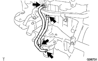
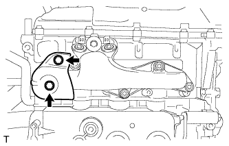
| 4. INSTALL OIL COOLER HOSE SUB-ASSEMBLY |
Install the 4 clamps and connect the oil cooler hose sub-assembly.
 |
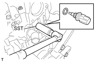
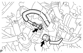
| 5. INSTALL ENGINE COOLANT TEMPERATURE SENSOR |
Using SST, install the engine coolant temperature sensor.
- SST
- 09817-33190
- Момент затяжки:
- 20 Н*м{204 кгс*см, 15 фунт-сила-футов}
 |
| 6. INSTALL HEATER OUTLET WATER HOSE |
Connect the heater outlet water hose with the clamp.
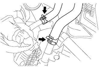 |
| 7. INSTALL HEATER INLET WATER HOSE |
Connect the heater inlet water hose with the clamp.
| 8. INSTALL NO. 1 RADIATOR HOSE |
Connect the the No. 1 radiator hose with the clamp.
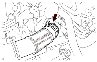 |
| 9. INSTALL MANIFOLD ABSOLUTE PRESSURE SENSOR HOSE |
Connect the turbo pressure sensor hose.
 |
| 10. INSTALL OIL LEVEL GAUGE GUIDE |
Install the oil level gauge guide with the bolt.
- Момент затяжки:
- 11 Н*м{112 кгс*см, 8 фунт-сила-футов}
| 11. INSTALL NO. 1 VALVE ROCKER ARM SUB-ASSEMBLY |
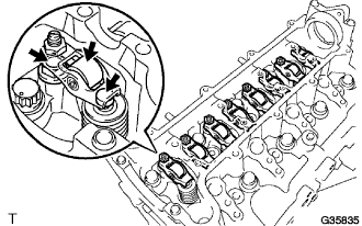 |
Apply engine oil to the stem end cap, valve rocker arm pivot top surface and valve rocker arm roller portion.
Install the 8 valve rocker arms.
| 12. INSTALL CAMSHAFT |
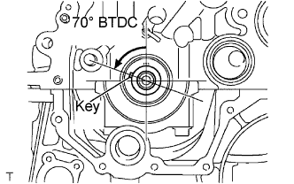 |
Turn the crankshaft to set the key in the 70° BTDC position.
Apply engine oil to the camshaft journal portion and cam portion.
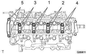
Examine the front marks and numbers and check that the sequence order is as shown in the illustration. Then, temporarily tighten the camshaft with the camshaft beating caps and bolts.
- ПРИМЕЧАНИЕ:
- Do not tilt the valve rocker arm when installing the camshaft onto the cylinder head.
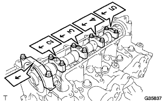 |
Using several steps, temporarily tighten the bolts in the sequence shown in the illustration, and then tighten the bolts to the specified torque.
- Момент затяжки:
- 19 Н*м{194 кгс*см, 14 фунт-сила-футов}
 |
| 13. INSTALL CHAIN SUB-ASSEMBLY |
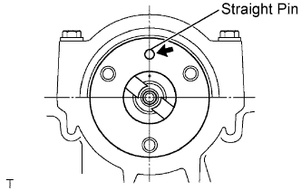
Turn the camshaft to set the straight pin in the position shown in the illustration.
 |
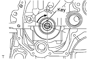
Turn the crankshaft to set the key in the position shown in the illustration.
 |
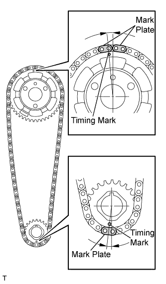
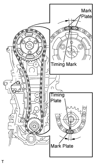
Align the yellow mark plate on the chain with the timing marks on the crankshaft timing sprocket and camshaft timing sprocket.
 |
Install the chain, camshaft timing sprocket and crankshaft sprocket together onto the engine.
 |
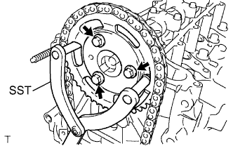
Using SST, fix the camshaft timing sprocket, and install the camshaft timing sprocket with 3 new bolts.
- SST
- 09960-10010(09962-01000,09963-01000)
- Момент затяжки:
- 20 Н*м{204 кгс*см, 15 фунт-сила-футов}
 |
| 14. INSTALL NO. 1 CHAIN VIBRATION DAMPER |
Install the chain vibration damper with the 2 bolts.
- Момент затяжки:
- 20 Н*м{204 кгс*см, 15 фунт-сила-футов}
 |
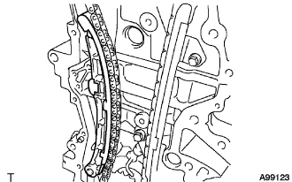
| 15. INSTALL CHAIN TENSIONER SLIPPER |
Install the chain tensioner slipper onto the cylinder block.
 |
| 16. INSTALL NO. 1 CHAIN TENSIONER ASSEMBLY |
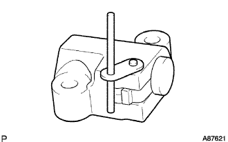
Pull up the stopper plate to unlock the plunger.
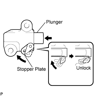 |
Push the plunger to the end with the plunger unlocked.
Pull down the stopper plate, with the plunger pushed to the end, to lock the plunger.
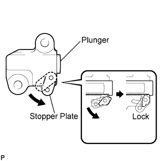 |
Insert a 2.5 mm (0.098 in.) diameter bar into the hole in the stopper plate with the plunger locked.
- УКАЗАНИЕ:
- If the stopper plate is not completely pulled down and a 2.5 mm (0.098 in.) diameter bar cannot be inserted, unlock and pull out the plunger slightly. The stopper plate will be completely pulled down and a 2.5 mm (0.098 in.) diameter bar can be inserted easily.
 |
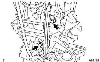
Install the chain tensioner with the 2 bolts.
- Момент затяжки:
- 9.0 Н*м{92 кгс*см, 80 фунт-сила-дюймов}
 |
Remove the 2.5 mm (0.098 in.) diameter bar from the chain tensioner.
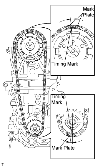
Check that the mark plate and timing mark are in the positions shown in the illustration.
 |
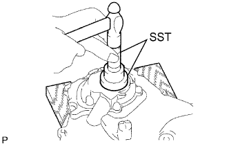
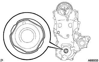
| 17. INSTALL OIL PUMP SEAL |
Using SST and a hammer, tap in a new oil seal until its surface is flush with the oil pump edge.
- SST
- 09223-22010
- ПРИМЕЧАНИЕ:
- Tap in the oil seal vertically.
 |
Apply MP grease to a new oil seal lip.
- ПРИМЕЧАНИЕ:
- Keep the lip free of foreign objects.
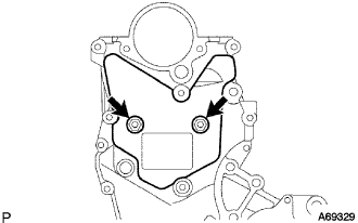
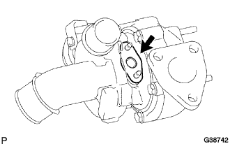
| 18. INSTALL OIL PUMP ASSEMBLY |
Install 2 new O-rings onto the 2 portions as shown in the illustration.
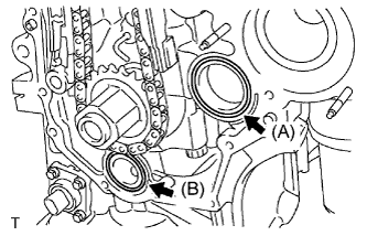 |
Apply seal packing to the engine body and oil pump as shown in the illustration below.
- Seal packing:
Position Item (A) Toyota Genuine Seal Packing 1282B, Three Bond 1282B or equivalent (B) Toyota Genuine Seal Packing Black, Three Bond 1207B or equivalent
- ПРИМЕЧАНИЕ:
- Remove any oil from the contact surface.
- Install the oil pan within 3 minutes, and tighten the bolts within 15 minutes of applying seal packing.
Align the keyway of the oil pump drive rotor with the rectangular portion of the crankshaft, then slide the oil pump into place.
 |
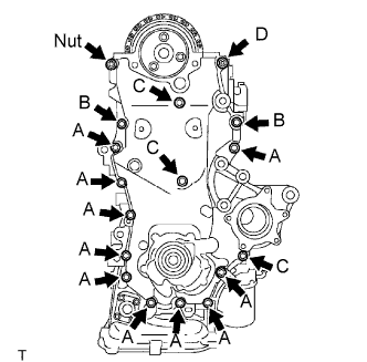
Install the oil pump assembly with the 16 bolts and nut as shown in the illustration.
- Момент затяжки:
- Bolt A:
- 11 Н*м{112 кгс*см, 8 фунт-сила-футов}
- Bolt B:
- 24 Н*м{245 кгс*см, 18 фунт-сила-футов}
- Bolt C:
- 11 Н*м{112 кгс*см, 8 фунт-сила-футов}
- Bolt D:
- 24 Н*м{245 кгс*см, 18 фунт-сила-футов}
- Nut:
- 24 Н*м{245 кгс*см, 18 фунт-сила-футов}
- ПРИМЕЧАНИЕ:
- Be careful not to let the chain come into contact with the seal packing when installing the oil pump.
- Install the engine mounting bracket RH and water pump within 15 minutes of installing the oil pump.
- УКАЗАНИЕ:
- The bolt lengths are as follows.
- Bolt A: 20 mm (0.79 in.)
- Bolt B: 30 mm (1.18 in.)
- Bolt C: 35 mm (1.38 in.)
- Bolt D (double ended bolt): 20 and 14 mm (0.79 and 0.55 in.)
 |
| 19. INSTALL NO. 2 TIMING CHAIN COVER |
Install the No. 2 timing chain cover with the 2 bolts.
- Момент затяжки:
- 5.5 Н*м{56 кгс*см, 49 фунт-сила-дюймов}
 |
| 20. INSTALL CRANK SHAFT DAMPER SUB-ASSEMBLY |
Align the key with the key groove of the crankshaft damper, and slide the crankshaft damper to the crankshaft.
 |
Using SST, secure the crankshaft damper.
- SST
- 09960-10010(09962-01000,09963-01000)
Tighten the bolt to the specified torque.
- Момент затяжки:
- 180 Н*м{1835 кгс*см, 133 фунт-сила-футов}
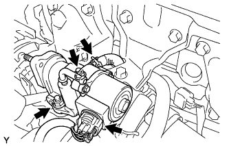
| 21. INSTALL VACUUM PUMP ASSEMBLY |
Нанесите моторное масло на 2 новых кольцевых уплотнения и установите их в вакуумный насос в сборе.
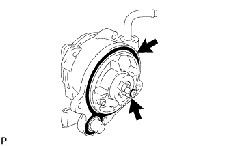 |
Нанесите моторное масло на маслопровод на кончике вакуумного насоса в сборе.
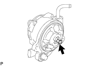 |
Установите вакуумный насос в сборе так, чтобы соединительный зубец (A) со стороны вакуумного насоса вошел в зацепление с канавкой (B) распредвала.
 |
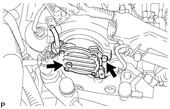
Закрепите вакуумный насос в сборе 2 новыми болтами.
- Момент затяжки:
- 21 Н*м{214 кгс*см, 15 фунт-сила-футов}
 |
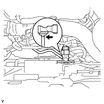
Подсоедините вакуумный шланг к вакуумному насосу в сборе и сдвиньте фиксатор.
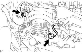 |
Подсоедините разъем датчика положения распредвала.
| 22. INSTALL CYLINDER HEAD COVER SUB-ASSEMBLY |
Install the cylinder head gasket onto the cylinder head cover.
 |
Apply seal packing to the 4 locations shown in the illustration, then install the cylinder head cover.
- Seal packing:
- Toyota Genuine Seal Packing Black, Three Bond 1207B or equivalent
- ПРИМЕЧАНИЕ:
- Remove any oil from the contact surface.
- Install the cylinder head cover within 3 minutes, and tighten the bolts within 15 minutes of applying the seal packing.
Temporarily tighten the cylinder head cover with the 12 bolts.
 |
Tighten the bolts to the specified torque as shown in the illustration.
- Момент затяжки:
- 13 Н*м{133 кгс*см, 10 фунт-сила-футов}
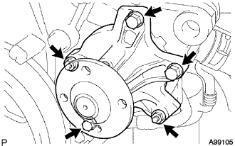
| 23. INSTALL WATER PUMP ASSEMBLY |
Install a new gasket and the water pump with the 3 bolts and 2 nuts.
- Момент затяжки:
- 11 Н*м{112 кгс*см, 8 фунт-сила-футов}
 |
| 24. INSTALL WATER PUMP PULLEY |
Temporarily install the water pump pulley with the 4 bolts.
 |
Using SST, hold the water pump pulley.
- SST
- 09960-10010(09962-01000,09963-00700)
Tighten the 4 bolts to the specified torque.
- Момент затяжки:
- 15 Н*м{153 кгс*см, 11 фунт-сила-футов}
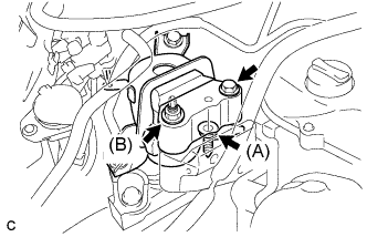
| 25. INSTALL ENGINE MOUNTING INSULATOR SUB-ASSEMBLY RH |
Install the engine mounting insulator RH with the 3 bolts.
- Момент затяжки:
- 95 Н*м{969 кгс*см, 70 фунт-сила-футов}
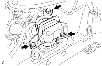 |
Install the engine mounting insulator RH to the engine mounting bracket with the bolt and 2 nuts.
- Момент затяжки:
- Bolt:
- 95 Н*м{969 кгс*см, 70 фунт-сила-футов}
- Nut(A):
- 95 Н*м{969 кгс*см, 70 фунт-сила-футов}
- Nut(B):
- 52 Н*м{530 кгс*см, 38 фунт-сила-футов}
 |
Install the air conditioner pipe bracket with the bolt and nut.
- Момент затяжки:
- 9.8 Н*м{100 кгс*см, 87 фунт-сила-дюймов}
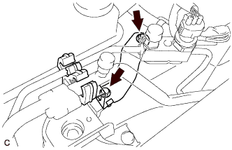 |
| 26. INSTALL GENERATOR ASSEMBLY |
Temporarily install the generator with the bolt.
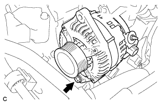 |
Temporarily install the fan belt adjusting slider with the bolt and nut, then move the generator toward the cylinder block and tighten the nut.
- Момент затяжки:
- 19 Н*м{189 кгс*см, 14 фунт-сила-футов}
 |
Install the connector.
 |
Install terminal B with the nut.
- Момент затяжки:
- 9.8 Н*м{100 кгс*см, 87 фунт-сила-дюймов}
Install the terminal cap.
| 27. INSTALL V-RIBBED BELT |
Temporarily install the v-ribbed belt onto each pulley.
- ПРИМЕЧАНИЕ:
- Before installing the V belt, check each pulley for any kind of liquid and chips.
- Check that the ribs of the V belt are correctly fitted into the grooves of the pulleys.
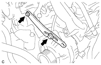
| 28. ADJUST V-RIBBED BELT |
Insert a bar between the generator and the engine. Pull the bar toward the front of the vehicle and adjust the tension.
 |
Tighten bolt A, then tighten bolt B.
- Момент затяжки:
- Bolt A:
- 19 Н*м{189 кгс*см, 14 фунт-сила-футов}
- Bolt B:
- 32 Н*м{326 кгс*см, 24 фунт-сила-футов}
 |
| 29. INSTALL EXHAUST MANIFOLD |
Install the exhaust manifold through a new gasket with the 5 nuts.
- Момент затяжки:
- 43 Н*м{438 кгс*см, 32 фунт-сила-футов}
 |
Install exhaust manifold heat insulator No. 1 with the 2 bolts.
- Момент затяжки:
- 6 Н*м{61 кгс*см, 53 фунт-сила-дюймов}
 |
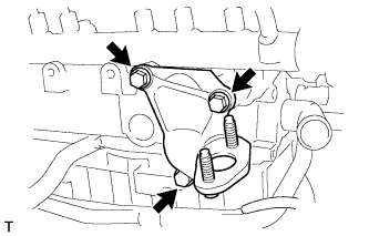
Install the manifold stay with the 2 bolts.
- Момент затяжки:
- 37 Н*м{377 кгс*см, 27 фунт-сила-футов}
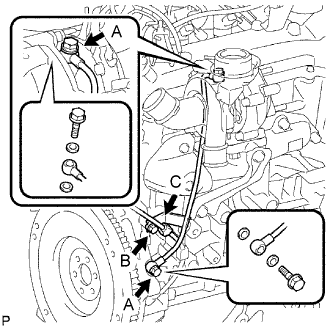
| 30. INSTALL TURBO OIL OUTLET PIPE |
Install a new gasket onto the cylinder block.
 |
Provisionally install the turbo oil outlet pipe with 2 new nuts.
 |
| 31. INSTALL TURBO CHARGER SUB-ASSEMBLY |
Install a new gasket onto the turbocharger.
 |
Install a new gasket onto the exhaust manifold.
 |
Install the turbocharger with the 3 nuts.
- Момент затяжки:
- 53 Н*м{540 кгс*см, 39 фунт-сила-футов}
 |
Connect the vacuum hose to the turbocharger.
Tighten 2 new nuts B.
- Момент затяжки:
- 11 Н*м{110 кгс*см, 8 фунт-сила-футов}
 |
Tighten 2 new nuts A.
- Момент затяжки:
- 14 Н*м{140 кгс*см, 10 фунт-сила-футов}
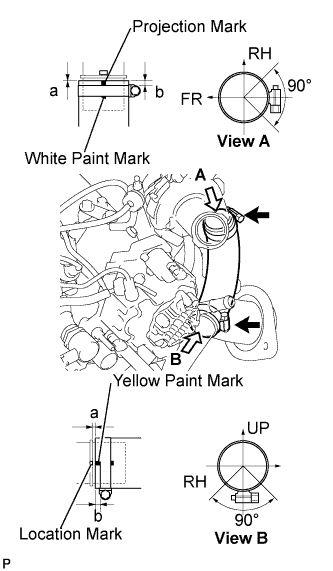
| 32. INSTALL NO. 1 AIR HOSE |
Install the intercooler air hose with the 2 hose clamps.
- Момент затяжки:
- 6.0 Н*м{60 кгс*см, 53 фунт-сила-дюймов}
- Specification:
Area Measurement a 0 to 2 mm (0 to 0.079 in.) b 2 to 5 mm (0.079 to 0.197 in.)
- ПРИМЕЧАНИЕ:
- Align the paint mark of the intercooler air hose with the location mark of the turbocharger.
- Align the paint mark of the intercooler air hose with the location mark of No. 1 air tube.
- Make sure that the hose clamp is at the correct angle when installing.
 |
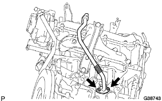
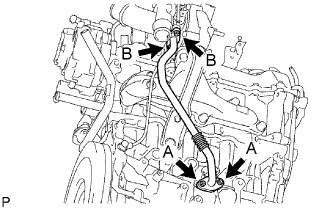
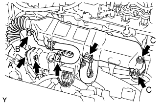
| 33. INSTALL TURBO OIL INLET PIPE |
Install 4 new gaskets and the turbo oil inlet pipe with 2 union bolts A.
- Момент затяжки:
- 24 Н*м{245 кгс*см, 18 фунт-сила-футов}
 |
Tighten bolt B.
- Момент затяжки:
- 11 Н*м{110 кгс*см, 8 фунт-сила-футов}
Install wire harness clamp C.
| 34. INSTALL EXHAUST MANIFOLD CONVERTER SUB-ASSEMBLY |
Install a new gasket onto the turbocharger.
 |
Temporarily install the exhaust manifold converter with 3 new nuts A.
 |
Provisionally install the manifold support bracket with the bolt B.
Tighten 3 nuts A.
- Момент затяжки:
- 26 Н*м{265 кгс*см, 19 фунт-сила-футов}
Tighten bolt B.
- Момент затяжки:
- 37 Н*м{375 кгс*см, 27 фунт-сила-футов}
| 35. INSTALL NO. 1 TURBO INSULATOR |
Install No. 1 turbo insulator with the 3 bolts.
- Момент затяжки:
- 6.0 Н*м{60 кгс*см, 53 фунт-сила-дюймов}
 |
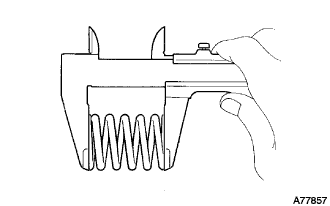
| 36. INSTALL FRONT EXHAUST PIPE ASSEMBLY |
Using vernier calipers, measure the free length of the compression springs.
Minimum (front) 41.5 mm (1.63 in.) Minimum (rear) 38.5 mm (1.52 in.) - УКАЗАНИЕ:
- If the length is less than minimum, replace the compression spring.
 |
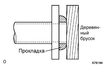
Using a plastic hammer and wooden block, tap in a new exhaust pipe gasket until its surface is flush with the exhaust manifold converter sub-assembly.
- ПРИМЕЧАНИЕ:
- Be careful with the installation direction of the gasket.
- Do not reuse the gasket.
- Do not damage the gasket.
- Do not push in the gasket by using the exhaust pipe when connecting it.
 |
Install the exhaust pipe supports, then install the front exhaust pipe assembly with the 2 compression springs and 2 bolts.
- Момент затяжки:
- 43 Н*м{439 кгс*см, 32 фунт-сила-футов}
 |
Using a plastic hammer and wooden block, tap in a new exhaust pipe gasket until its surface is flush with the front exhaust pipe assembly.
- ПРИМЕЧАНИЕ:
- Be careful with the installation direction of the gasket.
- Do not reuse the gasket.
- Do not damage the gasket.
- Do not push in the gasket by using the exhaust pipe when connecting it.
|
Install the 2 compression springs and 2 bolts, then connect the front exhaust pipe assembly to the center exhaust pipe assembly.
- Момент затяжки:
- 43 Н*м{439 кгс*см, 32 фунт-сила-футов}
 |
| 37. INSTALL SUPPLY PUMP ASSEMBLY |
- ПРИМЕЧАНИЕ:
- When installing, clean the seal surfaces of the fuel inlet pipe, supply pump and common rail.
Apply a light coat of engine oil to a new O-ring.
Install the O-ring onto the supply pump.
Install the supply pump drive coupling onto the supply pump drive shaft.
Temporarily install the supply pump with the 3 bolts.
 |
Remove the plastic bag and rubber band from the supply pump.
Connect the 2 connectors.
Connect the 3 fuel hoses.
| 38. INSTALL COMMON RAIL ASSEMBLY |
 |
Install the common rail assembly.
Connect the fuel hose.
Install the common rail with the 2 bolts.
- Момент затяжки:
- 26 Н*м{265 кгс*см, 19 фунт-сила-футов}
| 39. INSTALL FUEL INLET PIPE SUB-ASSEMBLY |
 |
- ПРИМЕЧАНИЕ:
- When replacing the supply pump, the fuel inlet pipe must also be replaced.
- Replace the fuel inlet pipe with a new one when the fuel inlet pipe has been removed and reinstalled more than 5 times.
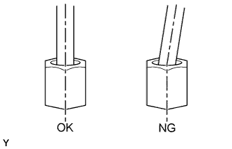
Temporarily install the fuel inlet pipe onto the supply pump and common rail.
- ПРИМЕЧАНИЕ:
- Install the pipe and union nut vertically, not at a tilt.
Tighten the supply pump with the 3 bolts.
- Момент затяжки:
- 20 Н*м{204 кгс*см, 15 фунт-сила-футов}
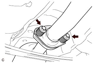
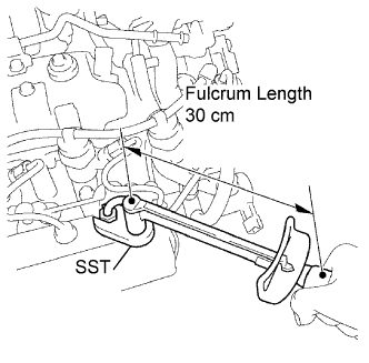
Using SST, tighten the fuel inlet pipe union nut of the fuel inlet pipe on the common rail side.
- SST
- 09023-38401
- Момент затяжки:
- With SST:
- 23 Н*м{235 кгс*см, 17 фунт-сила-футов}
- Without SST:
- 25 Н*м{255 кгс*см, 18 фунт-сила-футов}
- УКАЗАНИЕ:
- Use a torque wrench with a fulcrum length of 30 cm (11.81 in.).
- After the fuel inlet pipe has been reassembled, check that the used pipe has no deflection and is installed properly.
If it has deflection or could not be installed properly, replace the used pipe with a new one.
 |
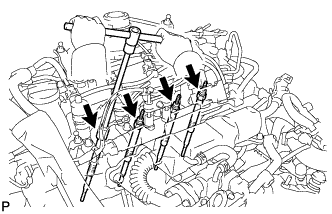
| 40. INSTALL INJECTOR ASSEMBLY |
- ПРИМЕЧАНИЕ:
- When installing, clean the sealing surface of the injector, injection pipe and common rail.
- If the injectors are replaced, the injection pipes must also be replaced.
- After the injection pipe has been removed and installed 5 times, the injection pipe needs to be replaced with a new one.
- Replace the injector with one with the same part number and install it onto the cylinder.
Using a cloth and solvent, wipe away any carbon from the sealing surface of the injector and injector installation hole, as shown in the illustration.
- ПРИМЕЧАНИЕ:
- Do not damage the sealing surface.
- Do not touch the injector nozzle.
 |
Install 4 new nozzle seats onto the cylinder head.
Install the injector onto the cylinder head.
- ПРИМЕЧАНИЕ:
- Fit the injectors into the seats.
Install the 4 nozzle holder clamp seats onto the cylinder head.
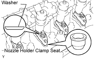 |
Install the 4 nozzle holder clamps onto the injectors.
Set the washer on the nozzle holder clamp, as shown in the illustration.
Temporarily tighten the 4 nozzle holder clamp bolts.
Temporarily install the 4 injection pipes onto the injector and common rail.
- ПРИМЕЧАНИЕ:
- Install the pipe and union nut vertically, not at a tilt.
|
Tighten the 4 nozzle holder clamp bolts.
- Момент затяжки:
- 26 Н*м{265 кгс*см, 19 фунт-сила-футов}
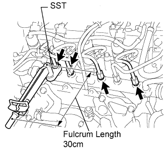
Using SST, tighten the injection pipe union nut of the injection pipe on the common rail side.
- SST
- 09023-38401
- Момент затяжки:
- With SST:
- 23 Н*м{235 кгс*см, 17 фунт-сила-футов}
- Without SST:
- 25 Н*м{255 кгс*см, 18 фунт-сила-футов}
- УКАЗАНИЕ:
- Use a torque wrench with a fulcrum length of 30 cm (11.81 in.).
- After the injection pipe has been reassembled, check that the used pipe has no deflection and is installed properly, then replace the used pipe with a new one.
 |
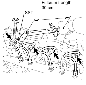
Using a wrench (13 mm), hold the injector steadily, and using SST, tighten the injection pipe union nut of the injection pipe on the injector side.
- SST
- 09023-38401
- Момент затяжки:
- With SST:
- 23 Н*м{235 кгс*см, 17 фунт-сила-футов}
- Without SST:
- 25 Н*м{255 кгс*см, 18 фунт-сила-футов}
- УКАЗАНИЕ:
- Use a torque wrench with a fulcrum length of 30 cm (11.81 in.).
- After the injection pipe has been reassembled, check that the used pipe has no deflection and is installed properly, then replace the used pipe with a new one.
 |
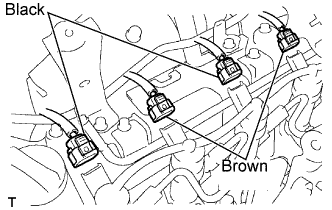
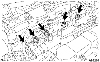
Connect the 4 injector connectors.
- ПРИМЕЧАНИЕ:
- Connect the black connectors to injectors No. 1 and No. 3, and brown connectors to No. 2 and No. 4.
 |
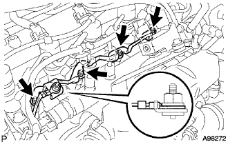
| 41. INSTALL NOZZLE LEAKAGE PIPE ASSEMBLY |
 |
- ПРИМЕЧАНИЕ:
- Never reuse the nozzle leakage pipe once it has been removed from the injectors and supply pump.
- Push the nozzle leakage pipe until it makes a click sound.
Install 5 new retainer springs onto the injectors and supply pump.
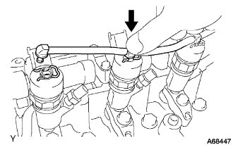
Push the new nozzle leakage pipe into each injector and supply pump.
| 42. INSTALL NO. 2 INJECTION PIPE CLAMP |
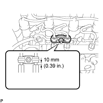 |
Install the No. 2 injection pipe clamp with the nut as shown in the illustration.
- Момент затяжки:
- 9.0 Н*м{92 кгс*см, 80 фунт-сила-дюймов}
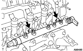
| 43. INSTALL NO. 1 INJECTION PIPE CLAMP |
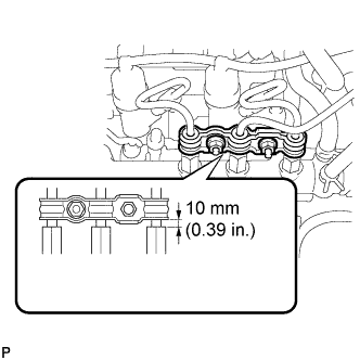 |
Install the No. 1 injection pipe clamp with the 2 nuts as shown in the illustration.
- Момент затяжки:
- 9.0 Н*м{92 кгс*см, 80 фунт-сила-дюймов}
| 44. INSTALL EGR PIPE CONNECTOR |
Install a new gasket, then install the EGR pipe connector with the 3 bolts.
- Момент затяжки:
- 20 Н*м{204 кгс*см, 15 фунт-сила-футов}
 |
| 45. INSTALL INTAKE AIR CONNECTOR |
Install a new gasket, then install the intake air connector with the 4 bolts.
- Момент затяжки:
- 20 Н*м{204 кгс*см, 15 фунт-сила-футов}
 |
Connect the vacuum hose and water hose.
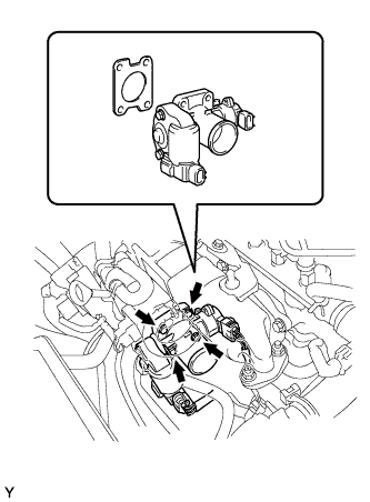
| 46. INSTALL DIESEL THROTTLE BODY ASSEMBLY |
Install a new gasket and the diesel throttle body with the 4 bolts.
- Момент затяжки:
- 20 Н*м{205 кгс*см, 15 фунт-сила-футов}
 |
Connect the throttle position sensor connector.
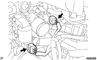 |
Connect the throttle control motor connector.
| 47. INSTALL EGR VALVE ASSEMBLY |
Install a new gasket.
 |
Install the EGR valve assembly with the 2 nuts.
- Момент затяжки:
- 20 Н*м{204 кгс*см, 15 фунт-сила-футов}
Connect the EGR valve connector and hose.
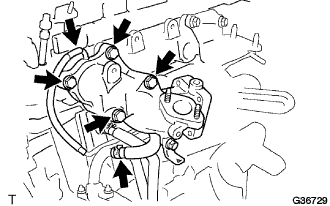
| 48. INSTALL EGR COOLER ASSEMBLY |
Install 2 new gaskets.
 |
Temporarily install the EGR cooler assembly with the bolt and 4 nuts, in the order described below.
Tighten bolt B.
- Момент затяжки:
- 11 Н*м{112 кгс*см, 8 фунт-сила-футов}
Tighten 2 nuts A.
- Момент затяжки:
- 11 Н*м{112 кгс*см, 8 фунт-сила-футов}
Tighten 2 nuts C.
- Момент затяжки:
- 20 Н*м{204 кгс*см, 15 фунт-сила-футов}
Connect the 2 water by-pass hoses.
| 49. INSTALL GLOW PLUG ASSEMBLY |
Clean the glow plug installation holes in the cylinder head.
 |
Using a deep socket wrench 10 mm, install the 4 glow plugs.
- Момент затяжки:
- :
- 13 Н*м{128 кгс*см, 9 фунт-сила-футов}
| 50. INSTALL NO. 1 GLOW PLUG CONNECTOR |
Install the No. 1 glow plug connector with the 4 nuts.
- Момент затяжки:
- 1.6 Н*м{15 кгс*см, 14 фунт-сила-дюймов}
 |
Connect the glow terminal with the nut.
- Момент затяжки:
- 3.8 Н*м{40 кгс*см, 34 фунт-сила-дюймов}
- ПРИМЕЧАНИЕ:
- Install the glow terminal in the correct direction.
Install the 5 screw grommets.
- ПРИМЕЧАНИЕ:
- Push the screw grommet into the threaded portion of the glow plug by hand, and then turn it clockwise.
 |
| 51. INSTALL VACUUM REGULATING VALVE ASSEMBLY |
Install the vacuum regulating valve with the 2 bolts.
- Момент затяжки:
- 3.4 Н*м{35 кгс*см, 30 фунт-сила-дюймов}
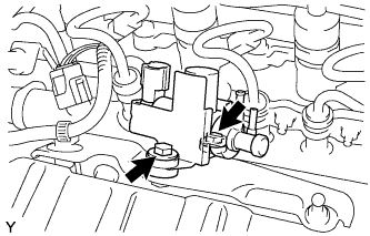 |
Connect the 2 vacuum hoses to the vacuum regulating valve.
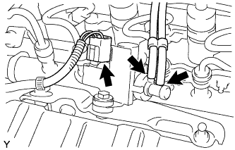 |
Connect the vacuum regulating valve connector.
| 52. INSTALL AIR CLEANER CASE SUB-ASSEMBLY |
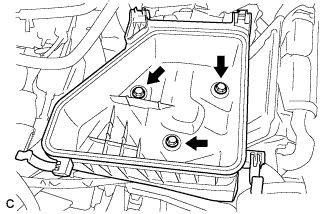
Install the air cleaner case sub-assembly with the 3 bolts.
- Момент затяжки:
- 7.0 Н*м{71 кгс*см, 62 фунт-сила-дюймов}
 |
| 53. INSTALL AIR CLEANER FILTER ELEMENT SUB-ASSEMBLY |
| 54. INSTALL AIR CLEANER CAP SUB-ASSEMBLY |
Install the air cleaner cap sub-assembly, and connect the 2 clamps and band.
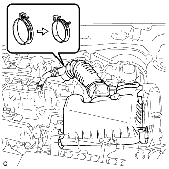 |
Connect the No. 2 ventilation hose.
Connect the mass air flow meter connector.
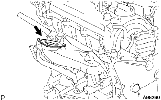
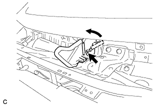
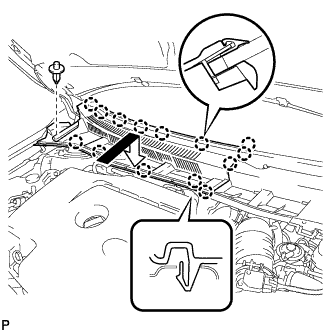
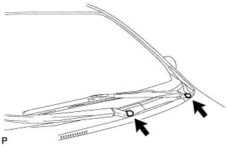
| 55. INSTALL COWL TOP PANEL OUTER (for Sedan) |
Установите наружную верхнюю панель кожуха и закрепите ее 10 болтами.
- Момент затяжки:
- 8,8 Н*м{90 кгс*см, 78 фунт-сила-дюймов}
 |
Отогните правую водозащитную пластину, как показано на рисунке, и введите в зацепление зажим.
 |
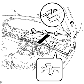
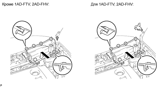
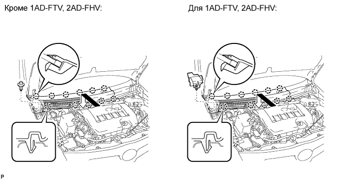
| 56. INSTALL COWL TOP PANEL OUTER (for Hatchback) |
Установите наружную верхнюю панель кожуха и закрепите ее 8 болтами.
- Момент затяжки:
- 8,8 Н*м{90 кгс*см, 78 фунт-сила-дюймов}
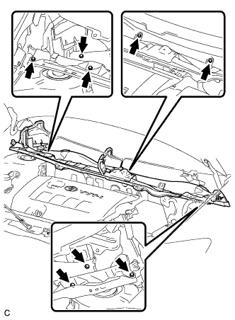 |
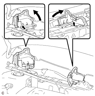
Отогните правую водозащитную пластину и брызгозащитное уплотнение воздуховода отопителя № 1 и отсоедините все зажимы, как показано на рисунке.
 |
| 57. INSTALL COWL BODY MOUNTING REINFORCEMENT LH (for Hatchback) |
Установите левый усилитель крепления кожуха к кузову и закрепите его 3 болтами.
- Момент затяжки:
- 8,8 Н*м{90 кгс*см, 78 фунт-сила-дюймов}
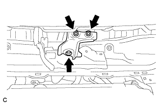 |
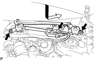
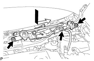
| 58. INSTALL FRONT WIPER MOTOR ASSEMBLY WITH LINK (for Sedan) |
Установите электродвигатель стеклоочистителя ветрового стекла с тягой в сборе и закрепите его 2 болтами.
- Момент затяжки:
- 5,5 Н*м{56 кгс*см, 49 фунт-сила-дюймов}
 |
Подсоедините разъем.
| 59. INSTALL FRONT WIPER MOTOR ASSEMBLY WITH LINK (for Hatchback) |
Установите электродвигатель стеклоочистителя ветрового стекла с тягой в сборе и закрепите его 2 болтами.
- Момент затяжки:
- 5,5 Н*м{56 кгс*см, 49 фунт-сила-дюймов}
 |
Подсоедините разъем.
| 60. INSTALL COWL TOP VENTILATOR LOUVER LH (for Sedan) |
Введите в зацепление фиксатор и 8 захватов и установите левую вентиляционную решетку в верхней части кожуха.
 |
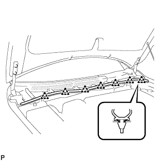
| 61. INSTALL COWL TOP VENTILATOR LOUVER RH (for Sedan) |
Введите в зацепление фиксатор и 14 захватов и установите правую вентиляционную решетку в верхней части кожуха.
 |
| 62. INSTALL COWL TOP VENTILATOR LOUVER LH (for Hatchback) |
Введите в зацепление фиксатор и 6 захватов и установите левую вентиляционную решетку в верхней части кожуха.
| 63. INSTALL COWL TOP VENTILATOR LOUVER RH (for Hatchback) |
Введите в зацепление фиксатор и 11 захватов и установите правую вентиляционную решетку в верхней части кожуха.
| 64. INSTALL HOOD TO COWL TOP SEAL |
Освободите 7 фиксаторов и отсоедините верхнее уплотнение между капотом и кожухом.
 |
| 65. INSTALL FRONT WIPER ARM AND BLADE SUB-ASSEMBLY LH |
Приведите в действие стеклоочиститель и остановите электродвигатель стеклоочистителя ветрового стекла в положении автоматического ограничения хода.
Очистите зубчатую часть рычага стеклоочистителя.
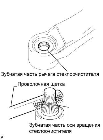 |
При повторной установке:
Почистите зубчатую часть оси вращения стеклоочистителя проволочной щеткой.
Установите левый рычаг переднего стеклоочистителя со щеткой в сборе, как показано на рисунке, и закрепите их гайкой.
- Момент затяжки:
- 26 Н*м{265 кгс*см, 19 фунт-сила-футов}
- УКАЗАНИЕ:
- Удерживайте шарнир рычага рукой, чтобы затянуть гайку.
Участок Измерение А 22,5–37,5 мм (0,89–1,48 дюйма)
 |
Приведите в действие передние стеклоочистители, одновременно распыляя омывающую жидкость на ветровое стекло. Убедитесь, что передние стеклоочистители работают надлежащим образом и не задевают кузов автомобиля.
| 66. INSTALL FRONT WIPER ARM AND BLADE SUB-ASSEMBLY RH |
Приведите в действие стеклоочиститель и остановите электродвигатель стеклоочистителя ветрового стекла в положении автоматического ограничения хода.
Очистите зубчатую часть рычага стеклоочистителя.
|
При повторной установке:
Почистите зубчатую часть оси вращения стеклоочистителя проволочной щеткой.
Установите правый рычаг переднего стеклоочистителя со щеткой в сборе, как показано на рисунке, и закрепите их гайкой.
- Момент затяжки:
- 26 Н*м{265 кгс*см, 19 фунт-сила-футов}
- УКАЗАНИЕ:
- Удерживайте шарнир рычага рукой, чтобы затянуть гайку.
Участок Измерение А 17,5–32,5 мм (0,69–1,28 дюйма)
 |
| 67. INSTALL FRONT WIPER ARM HEAD CAP |
Установите 2 крышки.
 |
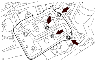
| 68. INSTALL BATTERY CARRIER |
Install the battery carrier assembly with the 6 bolts.
- Момент затяжки:
- 19 Н*м{194 кгс*см, 14 фунт-сила-футов}
 |
| 69. INSTALL BATTERY |
Install the battery and battery tray.
Install the battery clamp with the bolt and nut.
- Момент затяжки:
- Bolt:
- 17 Н*м{173 кгс*см, 13 фунт-сила-футов}
- Nut:
- 3.5 Н*м{36 кгс*см, 31 фунт-сила-дюймов}
 |
| 70. ADD ENGINE OIL |
Fill with fresh engine oil.
- Engine oil:
Oil Grade Oil Viscosity (SAE) - ACEA B1
- API CF-4 or CF (you may also use API CE or CD.)
- 5W-30
- 10W-30
- 15W-40
- 20W-50
- ACEA B1
- Capacity:
Item Fill amount Drain and refill with oil filter change 4.3 liters (4.5 US qts, 3.8 lmp. qts) Drain and refill without oil filter change 3.8 liters (4.0 US qts, 3.3 lmp. qts) Dry fill 4.8 liters (5.1 US qts, 4.2 lmp. qts)
| 71. ADD ENGINE COOLANT |
Tighten the radiator drain cock plug.
Add TOYOTA Super Long Life Coolant (SLLC) to the radiator reservoir filler opening.
- Standard capacity:
Item Specified Condition without Power heater 5.4 liters (5.7 US qts, 4.8 lmp. qts) with Power heater 5.8 liters (6.1 US qts, 5.1 lmp. qts)
- УКАЗАНИЕ:
- TOYOTA vehicles are filled with TOYOTA SLLC at the factory. In order to avoid damage to the engine cooling system and other technical problems, only use TOYOTA SLLC or similar high quality ethylene glycol based non-silicate, non-amine, non-nitrite, non-borate coolant with long-life hybrid organic acid technology (coolant with long-life hybrid organic acid technology consists of a combination of low phosphates and organic acids).
- Contact your TOYOTA dealer for further details.
- ПРИМЕЧАНИЕ:
- Never use water as a substitute for engine coolant.
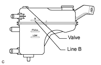
Remove the radiator cap and air-bleeding valve and add coolant to line B of the reservoir tank.
 |
Press the inlet and outlet radiator hoses several times by hand, and then check the level of the coolant.
If the coolant level is low, add coolant.
Install the cap and valve, and warm up the engine sufficiently.
Bleed air from the cooling system.
- ПРИМЕЧАНИЕ:
- Before starting the engine, turn the A/C switch OFF.
- Adjust the air conditioner set temperature to MAX (HOT).
- Adjust the air conditioner set blower to Lo.
Warm up the engine until the thermostat opens. While the thermostat is open, allow the coolant to circulate for several minutes.
- УКАЗАНИЕ:
- The thermostat opening timing can be confirmed by squeezing the inlet radiator hose by hand, and sensing vibrations when the engine coolant starts to flow inside the hose.
- ПРЕДОСТЕРЕЖЕНИЕ:
- When squeezing the radiator hose:
- Wear protective gloves.
- Be careful as the radiator hoses are hot.
- Keep your hands away from the radiator fan.
After the engine has warmed up, run the engine using the following cycle for at least 7 minutes: at 3000 rpm for 5 seconds, at idle speed for 45 seconds. (Repeat this cycle at least 8 times.)
Squeeze the inlet and outlet radiator hoses several times by hand to bleed air from the system.
- ПРЕДОСТЕРЕЖЕНИЕ:
- When squeezing the radiator hose:
- Wear protective gloves.
- Be careful as the radiator hoses are hot.
- Keep your hands away from the radiator fan.
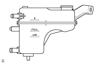
After the engine has cooled down, check that the coolant level is between FULL and LOW.
If the coolant level is low, add coolant to the reservoir tank F line.
 |
| 72. INSPECT ENGINE OIL LEVEL |
Warm up the engine. Then stop the engine and wait for 5 minutes.
Check that the engine oil level is between the 2 marks on the oil level gauge.
If low, check for leakage and top up oil to the upper mark.- ПРИМЕЧАНИЕ:
- Do not add engine oil to above the upper mark.
| 73. INSPECT FOR OIL LEAK |
| 74. INSPECT FOR ENGINE COOLANT LEAK |
- ПРЕДОСТЕРЕЖЕНИЕ:
- To avoid the danger of being burned, do not remove the radiator cap sub-assembly while the engine and radiator assembly are still hot. Thermal expansion will cause hot engine coolant and steam to blow out from the radiator assembly.
Fill the radiator assembly with engine coolant, then attach a radiator cap tester.
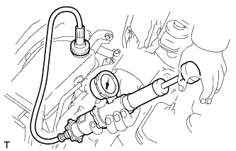 |
Pump it to 108 kPa (1.1 kgf/cm2, 15.6 psi), then check that the pressure does not drop.
If the pressure drops, check the hoses, radiator assembly and water pump assembly for leakage. If there are no signs or traces of external engine coolant leakage, check the heater core, cylinder block and head.
| 75. INSPECT FOR FUEL LEAK |
- УКАЗАНИЕ:
- Using the intelligent tester to perform Active Tests allow relays, VSVs, actuators and other items to be operated without removing any parts. This non-intrusive functional inspection can be very useful because intermittent operation may be discovered before parts or wiring is disturbed. Performing Active Tests early in troubleshooting is one way to save diagnostic time. Data List information can be displayed while performing Active Tests.
- The Data List can be displayed during Active Tests.
Connect an intelligent tester to the DLC3.
Turn the ignition switch to the ON position.
Turn the tester on.
Enter the following menu items: Powertrain / Engine and ECT / Active Test.
Perform the Active Test.
Tester Display Test Part Control Range Diagnostic Notes Active the fuel leak test Pressurize common rail internal fuel pressure, in order to see if fuel leaks ON/OFF - Fuel pressure inside common rail pressurized to 135 MPa and engine speed increased to 2000 rpm when ON selected
- Above conditions preserved while test ON
- Fuel pressure inside common rail pressurized to 135 MPa and engine speed increased to 2000 rpm when ON selected
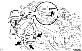
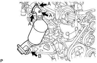
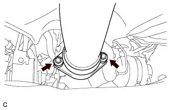
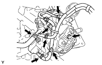
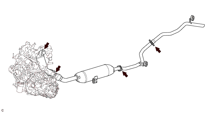
| 76. INSPECT FOR EXHAUST GAS LEAK |
Check that there are no exhaust gas leaks from the points (jointed parts of the exhaust pipes and installed parts of each sensor) shown in the illustration.
| 77. INSTALL NO. 1 ENGINE COVER |
Fit the 4 retainers and install the No. 1 engine cover.
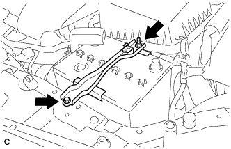
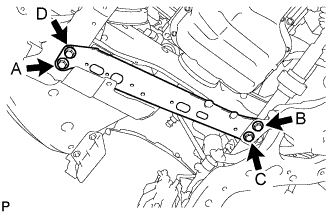
| 78. INSTALL FRONT SUSPENSION MEMBER REINFORCEMENT RH |
Установите правое усиление элемента передней подвески и закрепите его 4 болтами.
- Момент затяжки:
- 96 Н*м{979 кгс*см, 71 фунт-сила-футов}
- ПРИМЕЧАНИЕ:
- Предварительно затяните болты A и B, а затем полностью затяните 4 болта в следующем порядке: C, B, D и A.
 |
| 79. INSTALL ENGINE UNDER COVER REAR RH |
Install the engine under cover rear RH with the 5 clips.
| 80. INSTALL NO. 1 ENGINE UNDER COVER |
| 81. INSTALL FRONT WHEEL RH |
- Момент затяжки:
- 103 Н*м{1050 кгс*см, 76 фунт-сила-футов}