Блок Двигателя -- Повторная Сборка |
| 1. INSTALL ENGINE BALANCER ASSEMBLY |
Align the drive and driven gear's timing marks (1 dot mark each) by turning the crankshaft with a wrench.
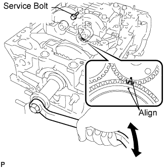 |
Set the engine balancer.
 |
Install the engine balancer bolts.
- УКАЗАНИЕ:
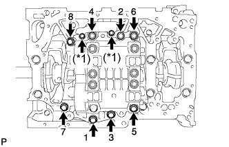
- The engine balancer bolts are tightened in 2 progressive steps.
Step 1
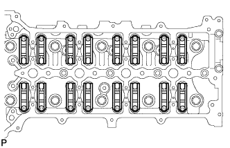
Install and uniformly tighten the 8 bolts in several passes in the sequence shown.
- Момент затяжки:
- 50 Н*м{510 кгс*см, 37 фунт-сила-футов}
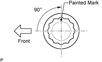
Step 2
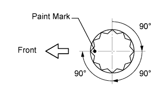
Mark the front of the engine balancer bolts with paint.
Retighten the engine balancer bolts by 90° as shown.
Check that the painted mark is now at a 90° angle to the front.
 |
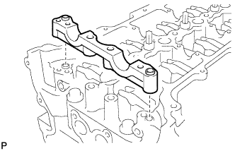
Install the oil baffle plate with the 2 bolts (*1).
- Момент затяжки:
- 9.0 Н*м{92 кгс*см, 80 фунт-сила-дюймов}
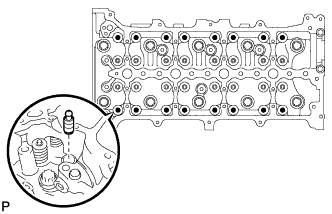
Remove the service bolt from the engine balancer.
| 2. INSTALL CYLINDER HEAD SUB-ASSEMBLY |
Set the crankshaft pulley bolt to the crankshaft.
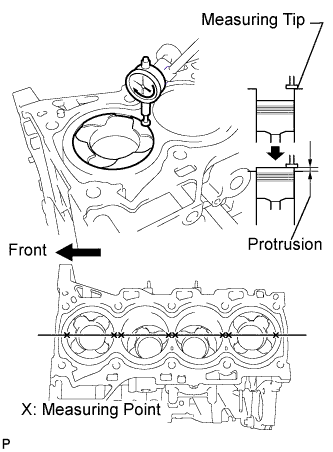
Check the piston protrusions for each cylinder.
Clean the cylinder block with solvent.
Set the piston of the cylinder to be measured to slightly before TDC.
Place a dial indicator on the cylinder block, and set the measuring tip as shown in the illustration.
Set the dial indicator at 0 mm (0 in.).
- УКАЗАНИЕ:
- Make sure that the measuring tip is flat against the cylinder block gasket surface and piston head when taking the measurements.
Find where the piston head protrudes most by slowly turning the crankshaft clockwise and counterclockwise.
Measure the piston protrusion value of each cylinder at 2 places as shown in the illustration, making a total of 8 measurements.
- Standard piston protrusion:
- 0.300 to 0.560 mm (0.0118 to 0.0221 in.)
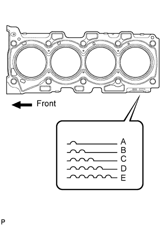
Select the size of a new cylinder head gasket based on the largest piston protrusion value of the 8 measurements.
Select a new cylinder head gasket.
Select the largest piston protrusion value from the measurements and then select a new appropriate gasket according to the table below.
- Piston protrusion:
Piston protrusion value Select gasket size 0.300 to 0.355 mm (0.0118 to 0.0140 in.) Size A 0.355 to 0.405 mm (0.0140 to 0.0159 in.) Size B 0.405 to 0.455 mm (0.0159 to 0.0179 in.) Size C 0.455 to 0.505 mm (0.0179 to 0.0199 in.) Size D 0.505 to 0.560 mm (0.0199 to 0.0221 in.) Size E
- УКАЗАНИЕ:
- Cylinder head gaskets are marked A, B, C, D or E accordingly.
- Cylinder head gasket thickness:
Cutout Mark Cylinder head gasket thickness A 1.00 to 1.10 mm (0.0394 to 0.0433 in.) B 1.05 to 1.15 mm (0.0413 to 0.0453 in.) C 1.10 to 1.20 mm (0.0433 to 0.0472 in.) D 1.15 to 1.25 mm (0.0453 to 0.0492 in.) E 1.20 to 1.30 mm (0.0472 to 0.0512 in.)
 |
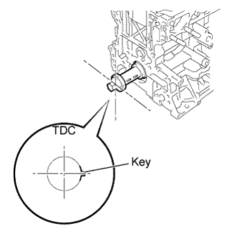
Set the crankshaft to the following conditions by turning the crankshaft pulley bolt.
The No. 1 piston is set to approximately 90° ATDC/compression.
The key is set to the position shown in the illustration.
 |
Place the cylinder head gasket in position on the cylinder block.
- ПРИМЕЧАНИЕ:
- Be careful of the installation direction.
Place the cylinder head on the cylinder block.
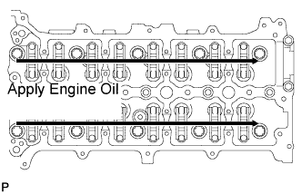
Apply a light coat of engine oil to the following: 1) the threads of the cylinder head bolts, 2) under the heads of the cylinder head bolts, and 3) the washers.
Install the cylinder head bolts.
- УКАЗАНИЕ:
- For new bolts, perform steps 1 to 3. For used bolts, perform only step 1.
- If any bolt is broken or deformed, replace it.
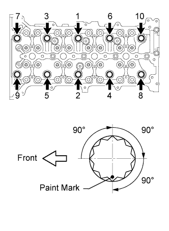
Step 1:
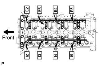
Install and uniformly tighten the 10 cylinder head bolts, in several steps in the sequence shown in the illustration.
- Момент затяжки:
- 50 Н*м{510 кгс*см, 37 фунт-сила-футов}
- УКАЗАНИЕ:
- If any cylinder head bolt does not meet the torque specification, replace the cylinder head bolt.
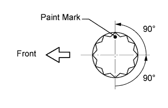
Mark the front of the cylinder head bolts with paint.
Retighten the cylinder head bolts by 90° in the sequence shown in the illustration.
Perform the step above twice.
Check that the paint marks are positioned as shown in the illustration.
Step 2:
Loosen the cylinder head bolts by 90° in the sequence shown in the illustration.
Perform the step above again.
Check that the paint marks are positioned as shown in the illustration.
Step 3:
Retighten the cylinder head bolts by 90° in the sequence shown in the illustration.
Perform the step above twice.
Check that the paint marks are positioned as shown in the illustration.
| 3. INSTALL VALVE LASH ADJUSTER ASSEMBLY |
Be sure to inspect the valve lash adjuster before installing it (see page Нажмите здесь).
 |
Install the 16 valve lash adjusters.
- ПРИМЕЧАНИЕ:
- Install the valve lash adjusters to their original positions.
| 4. INSTALL VALVE ROCKER ARM |
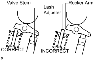
Set the 16 valve rocker arms to the 16 valve lash adjusters.
- ПРИМЕЧАНИЕ:
- Before and after setting the No. 1 camshaft and No. 2 camshaft, firmly set the valve rocker arms to the valve lash adjusters.
 |
| 5. INSTALL NO. 1 CAMSHAFT |
Install the No. 2 camshaft bearing cap.
 |
Apply clean engine oil to the cam of each camshaft, journals of the cylinder head and the rollers of the valve rocker arms.
 |
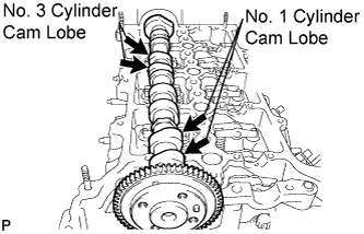
Place the No. 2 camshaft on the cylinder head as shown in the illustration so that the No. 1 and No. 3 cylinder cam lobes face upward.
- ПРИМЕЧАНИЕ:
- Before and after setting the No. 1 camshaft and No. 2 camshaft, check that the valve rocker arms are firmly set to the valve lash adjusters.
 |
Align the No. 1 camshaft and No. 2 camshaft timing marks (1 dot mark each).
 |
Place the No. 1 camshaft on the cylinder head.
Set the No. 1 camshaft bearing cap on the cylinder head.
Set the No. 3 camshaft bearing caps on the cylinder head as shown in the illustration.
- УКАЗАНИЕ:
- Confirm the marks and numbers on the camshaft bearing caps and place them each in the proper position and direction.
 |
Set the oil delivery pipes, bolts and union bolts.
Temporarily install the 2 union bolts.
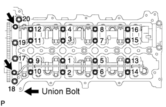 |
Install the camshaft bearing cap bolts by uniformly tightening the bolts in the sequence shown in the illustration.
- ПРИМЕЧАНИЕ:
- Be careful not to deform the oil delivery pipe LH when tightening the bearing cap bolts.
- Момент затяжки:
- 10 Н*м{102 кгс*см, 7 фунт-сила-футов}for 1 to 16
- 25 Н*м{255 кгс*см, 18 фунт-сила-футов}for 17 to 20
Tighten the 2 union bolts.
- ПРИМЕЧАНИЕ:
- Be careful not to deform the camshaft oil delivery pipe when tightening the union bolts.
- Момент затяжки:
- 17 Н*м{173 кгс*см, 13 фунт-сила-футов}
| 6. INSTALL CRANKSHAFT TIMING SPROCKET |
Install the crankshaft timing sprocket and oil pump drive gear.
| 7. INSTALL CAMSHAFT TIMING SPROCKET |
Set the No. 2 camshaft and crankshaft to TDC.
Turn the No. 2 camshaft to set the straight pin to the position shown in the illustration.
Turn the crankshaft timing sprocket in the opposite direction of the engine revolution direction to set the timing mark to the position shown in the illustration.
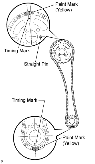 |
Align one of the chain's paint marks with the timing mark of the camshaft timing sprocket, and set that part of the chain to the camshaft timing sprocket.
- УКАЗАНИЕ:
- Do not set the camshaft timing sprocket to the cylinder head yet.
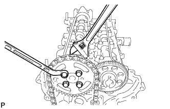
Align the chain's other paint mark to the crankshaft timing sprocket, and set that part of the chain to the crankshaft timing sprocket. Then install the camshaft timing sprocket (together with the remainder of the chain) onto the No. 2 camshaft's straight pin. Temporarily install the sprocket with the 4 bolts.
While holding the hexagonal portion of the No. 2 camshaft, tighten the 4 bolts to install the camshaft timing sprocket to the No. 2 camshaft.
- Момент затяжки:
- 20 Н*м{204 кгс*см, 15 фунт-сила-футов}
 |
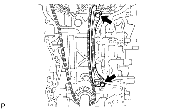
| 8. INSTALL NO. 1 CHAIN VIBRATION DAMPER |
Install the No. 1 chain vibration damper with the 2 bolts.
- Момент затяжки:
- 21 Н*м{214 кгс*см, 15 фунт-сила-футов}
- УКАЗАНИЕ:
- Before installing the No. 1 chain vibration damper, rotate the crankshaft counterclockwise to loosen the chain. After the installation, return the crankshaft to TDC.
 |
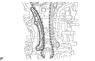
| 9. INSTALL CHAIN TENSIONER SLIPPER |
Install the tensioner slipper.
 |
| 10. INSTALL NO. 1 CHAIN TENSIONER ASSEMBLY |
Move the stopper plate upward to release the lock, and push the plunger deep into the tensioner (*1).
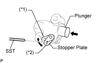 |
Move the stopper plate downward to set the lock, and insert SST into the stopper plate hole (*2).
- SST
- 09240-00020(09242-00250)
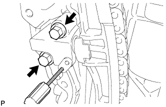
Install the No. 1 chain tensioner with the 2 bolts.
- Момент затяжки:
- 9.0 Н*м{92 кгс*см, 80 фунт-сила-дюймов}
 |
Remove SST.
| 11. CHECK NO. 1 CYLINDER TDC/COMPRESSION |
Rotate the crankshaft pulley approximately 720°.
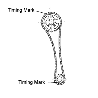 |
Check that the sprockets' timing marks are at No. 1 cylinder TDC, as shown in the illustration.
If not, remove the chain and reinstall it.
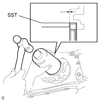
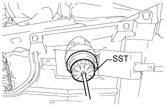
| 12. INSTALL TIMING GEAR CASE OR TIMING CHAIN CASE OIL SEAL |
Apply MP grease to a new oil seal lip.
- ПРИМЕЧАНИЕ:
- Keep the lip free of foreign objects.
Using SST and a hammer, tap in a new oil seal until its surface is flush with the oil pump edge.
- SST
- 09226-10010
- ПРИМЕЧАНИЕ:
- Do not tap the oil seal at an angle.
- Wipe off extra grease on the crankshaft.
 |
| 13. INSTALL TIMING CHAIN COVER SUB-ASSEMBLY |
Install a new gasket and O-ring to the timing chain cover as shown in the illustration.
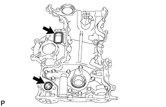 |
Apply seal packing to the timing chain cover as shown in the illustration.
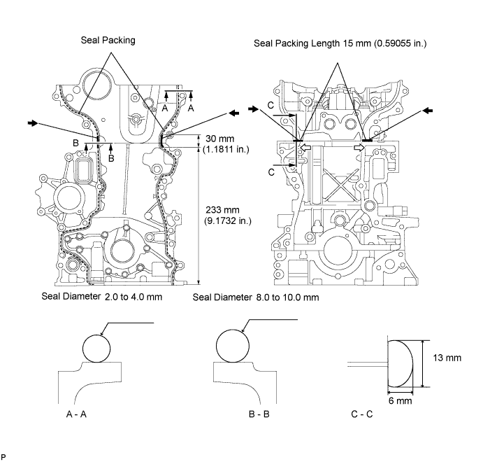
- Seal packing:
- Toyota Genuine Seal Packing Black, Three Bond 1207B or equivalent
- Standard seal diameter:
Position Specified Condition A - A 2.0 to 4.0 mm (0.079 to 0.157 in.) B - B 8.0 to 10.0 mm (0.315 to 0.394 in.) C - C Width: 13 mm (0.512 in.)
Height: 6 mm (0.236 in.)
- ПРИМЕЧАНИЕ:
- Be sure to clean and degrease the contact surfaces, especially the 4 areas indicated by the arrows in the illustration.
- When the contact surfaces are wet, wipe them with an oil-free cloth before applying seal packing.
- When applying seal packing to area C - C, apply it in the direction of the white arrows in the illustration.
- Install the crankcase within 3 minutes and tighten the bolts within 15 minutes after applying seal packing.
- Do not start the engine for at least 4 hours after installing.
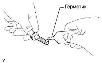
Apply adhesive to the 4 bolts.
- Adhesive:
- Toyota Genuine Adhesive 1324, Three Bond 1324 or equivalent
- УКАЗАНИЕ:
- Bolt length: 37.5 mm (1.476 in.)
 |
Temporarily install the timing chain cover with the 4 bolts.
 |
Temporarily install a new seal washer and bolt A.
- УКАЗАНИЕ:
- Bolt length: 67.5 mm (2.657 in.)
Temporarily install the 8 bolts.
- УКАЗАНИЕ:
- Bolt length: 37.5 mm (1.476 in.)
Using several steps, tighten the 13 bolts.
- Момент затяжки:
- 31.5 Н*м{321 кгс*см, 23 фунт-сила-футов}for except bolt A
- 21 Н*м{214 кгс*см, 15 фунт-сила-футов}for bolt A
Using a 10 mm socket hexagon wrench, install a new gasket and the timing chain cover tight plug.
- Момент затяжки:
- 19 Н*м{194 кгс*см, 14 фунт-сила-футов}
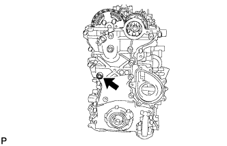 |
| 14. INSTALL WATER PUMP ASSEMBLY |
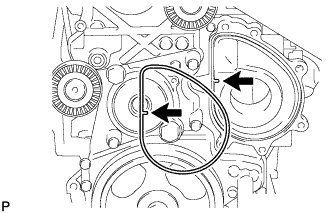
Install a new gasket onto the timing chain cover as shown in the illustration.
 |
Clean the 7 bolts and 7 bolt holes.
Apply adhesive to 2 or 3 threads of the bolt labeled A.
- Adhesive:
- Toyota Genuine Adhesive 1324, Three Bond 1324 or equivalent
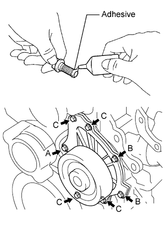 |
Temporarily install the water pump with the 7 bolts.
- Standard bolt length:
Item Specified Condition Bolt A and C 45 mm (1.77 in.) Bolt B 30 mm (1.18 in.)
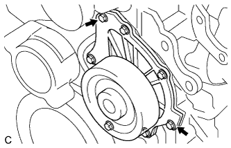
Tighten the 2 bolts indicated by the arrows in the illustration. Then tighten the other bolts.
- Момент затяжки:
- 32 Н*м{326 кгс*см, 24 фунт-сила-футов}
 |
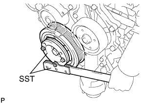
| 15. INSTALL CRANKSHAFT PULLEY |
Align the keyway of the pulley with the key located on the crankshaft, then slide the pulley into place.
Using SST, install the pulley bolt.
- SST
- 09213-58013
09330-00021
- Момент затяжки:
- 250 Н*м{2549 кгс*см, 184 фунт-сила-футов}
 |
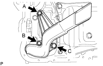
| 16. INSTALL OIL STRAINER SUB-ASSEMBLY |
Install a new O-ring and the oil strainer with the 3 bolts.
- Момент затяжки:
- 9.0 Н*м{92 кгс*см, 80 фунт-сила-дюймов}for bolt A and B
- 42 Н*м{428 кгс*см, 31 фунт-сила-футов}for bolt C
 |
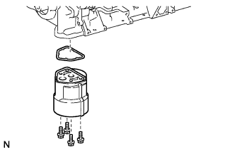
| 17. INSTALL OIL FILTER BRACKET |
Install a new gasket and the oil filter bracket with the 4 bolts.
- Момент затяжки:
- 9.0 Н*м{92 кгс*см, 80 фунт-сила-дюймов}
 |
| 18. INSTALL OIL FILTER ELEMENT |
Clean the inside of oil filter cap, threads, and O-ring groove.
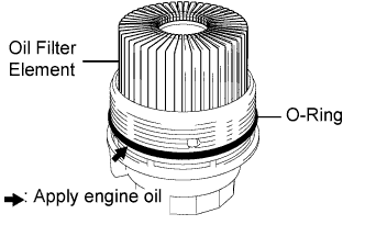 |
Apply a small amount of engine oil to a new O-ring and install it to the oil filter cap assembly.
Install a new oil filter element into the oil filter cap assembly.
Remove any dirt or foreign matter from the contact surfaces of the oil filter cap assembly (with oil filter element) and oil filter bracket.
Install the oil filter cap assembly (with oil filter element) to the oil filter bracket.
| 19. INSTALL OIL FILTER CAP ASSEMBLY |
Using SST, tighten the oil filter cap.
- SST
- 09228-06501
- Момент затяжки:
- 40 Н*м{408 кгс*см, 30 фунт-сила-футов}
- ПРИМЕЧАНИЕ:
- Check and clean the oil filter installation surface.
 |
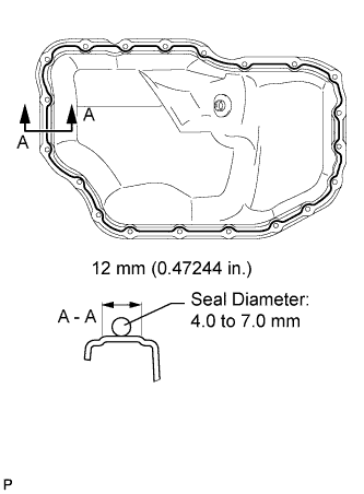
| 20. INSTALL NO. 2 OIL PAN SUB-ASSEMBLY |
Apply seal packing in a continuous bead as shown in the illustration.
- Seal packing:
- Toyota Genuine Seal Packing Black, Three Bond 1207B or equivalent
- Standard seal diameter:
- 4.0 to 7.0 mm (0.157 to 0.276 in.)
- ПРИМЕЧАНИЕ:
- Remove any oil from the contact surfaces.
- Install the oil pan within 3 minutes and tighten the bolts within 10 minutes after applying seal packing.
- Do not start the engine for at least 4 hours after installation.
 |
Install the oil pan with the 18 bolts and 2 nuts.
- Момент затяжки:
- 10.5 Н*м{107 кгс*см, 8 фунт-сила-футов}
 |
Install a new gasket and the drain plug.
- Момент затяжки:
- 38 Н*м{387 кгс*см, 28 фунт-сила-футов}
| 21. INSTALL CYLINDER HEAD COVER SUB-ASSEMBLY |
| 22. INSTALL OIL FILLER CAP SUB-ASSEMBLY |