Блок Двигателя -- Проверка |
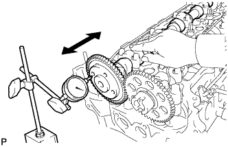
| 1. INSPECT CHAIN SUB-ASSEMBLY |
Using a spring scale, pull the chain with a force of 147 N (15 kgf, 33 lbf) as shown in the illustration.
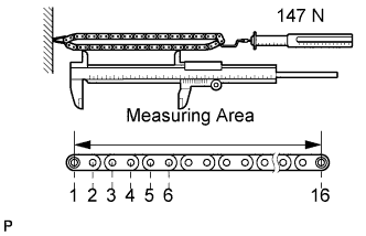 |
Using a vernier caliper, measure the length of 16 pins.
- Maximum chain elongation:
- 144.3 mm (5.681 in.)
- ПРИМЕЧАНИЕ:
- Perform the measurement at 3 random places.
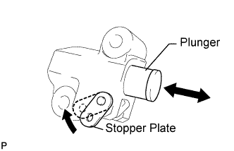
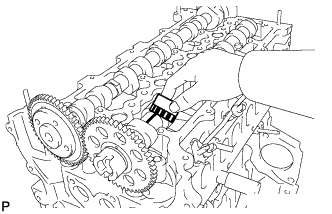
| 2. INSPECT NO. 1 CHAIN TENSIONER ASSEMBLY |
Move the stopper plate upward to release the lock. Push the plunger and check that it moves smoothly.
 |
| 3. INSPECT CAMSHAFT TIMING SPROCKET |
Place the chain around the sprocket.
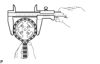 |
Using a vernier caliper, measure the sprocket diameter with the chain.
- Minimum sprocket with chain diameter:
- 132.6 mm (5.220 in.)
- УКАЗАНИЕ:
- The vernier caliper must contact the chain rollers for the measurement.
- If the diameter is less than the minimum, replace the chain and sprocket.
| 4. INSPECT CRANKSHAFT TIMING SPROCKET |
Place the chain around the sprocket.
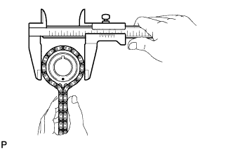 |
Using a vernier caliper, measure the sprocket diameter with the chain.
- Minimum sprocket with chain diameter:
- 69.1 mm (2.720 in.)
- УКАЗАНИЕ:
- The vernier caliper must contact the chain rollers for the measurement.
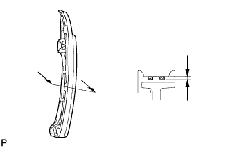
| 5. INSPECT CHAIN TENSIONER SLIPPER |
Using a vernier caliper, measure the tensioner slipper wear.
- Maximum wear:
- 1.0 mm (0.039 in.)
 |
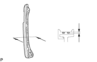
| 6. INSPECT NO. 1 CHAIN VIBRATION DAMPER |
Using a vernier caliper, measure the vibration damper wear.
- Maximum wear:
- 1.0 mm (0.039 in.)
 |
| 7. INSPECT VALVE LASH ADJUSTER ASSEMBLY |
- ПРИМЕЧАНИЕ:
- Keep the lash adjuster free from dirt and foreign objects.
- Use only clean engine oil.
Place the lash adjuster into a container full of new engine oil.
Insert SST's tip into the lash adjuster's plunger and use the tip to press down on the check ball inside the plunger.
- SST
- 09276-75010
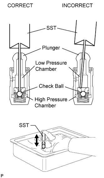 |
Squeeze SST and the lash adjuster together to move the plunger up and down 5 to 6 times.
Check the movement of the plunger and bleed air.
- OK:
- Plunger moves up and down.
- ПРИМЕЧАНИЕ:
- When bleeding high-pressure air from the compression chamber, make sure that the tip of SST is actually pressing the check ball as shown in the illustration. If the check ball is not pressed, air will not bleed.
After bleeding the air, remove SST. Then try to quickly and firmly press the plunger with your fingers.
- OK:
- Plunger can be pressed 3 times.
| 8. INSPECT NO. 1 CAMSHAFT |
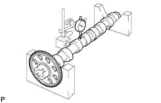
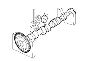
Check the camshaft for runout.
Place the camshaft on V-blocks.
Using a dial indicator, measure the circle runout at the center journal.
- Maximum circle runout:
- 0.03 mm (0.0012 in.)
 |
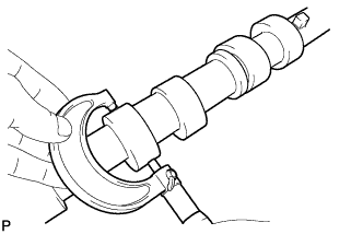
Using a micrometer, measure the cam lobe height.
- Standard cam lobe height:
- 37.559 to 37.759 mm (1.4787 to 1.4866 in.)
- Minimum cam lobe height:
- 37.559 mm (1.4787 in.)
 |
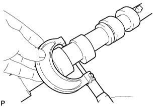
Using a micrometer, measure the journal diameter.
- Standard journal diameter:
- 26.969 to 26.985 mm (1.0617 to 1.0624 in.)
 |
| 9. INSPECT NO. 2 CAMSHAFT |
Check the camshaft for runout.
Place the camshaft on V-blocks.
Using a dial indicator, measure the circle runout at the center journal.
- Maximum circle runout:
- 0.03 mm (0.0012 in.)
 |
Using a micrometer, measure the cam lobe height.
- Standard cam lobe height:
- 38.270 to 38.470 mm (1.5067 to 1.5146 in.)
- Minimum cam lobe height:
- 38.270 mm (1.5067 in.)
|
Using a micrometer, measure the journal diameter.
- Standard journal diameter:
- 26.969 to 26.985 mm (1.0612 to 1.0624 in.)
|
| 10. INSPECT CAMSHAFT OIL CLEARANCE |
Clean the bearing caps and camshaft journals.
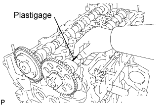 |
Place the camshafts on the cylinder head.
Lay a strip of Plastigage across each of the camshaft journals.
Install the bearing caps (see page Нажмите здесь).
- ПРИМЕЧАНИЕ:
- Do not turn the camshaft.
Remove the bearing caps (see page Нажмите здесь).
Measure the Plastigage at its widest point.
- Standard journal clearance:
- 0.025 to 0.062 mm (0.0010 to 0.0024 in.)
- Maximum oil clearance:
- 0.062 mm (0.0024 in.)
 |
Completely remove the Plastigage.
| 11. INSPECT CAMSHAFT THRUST CLEARANCE |
Install the No. 2 camshaft and No. 1 camshaft (see page Нажмите здесь).
 |
Using a dial indicator, measure the thrust clearance while moving the camshaft back and forth.
- Standard thrust clearance:
- 0.035 to 0.160 mm (0.0014 to 0.0063 in.)
- Maximum thrust clearance:
- 0.160 mm (0.0063 in.)
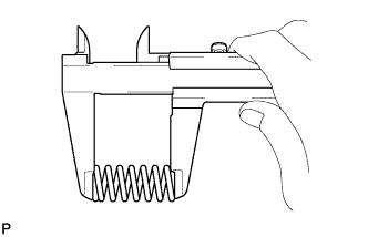
| 12. INSPECT COMPRESSION SPRING |
Using a vernier caliper, measure the free length of the compression spring.
- Standard free length:
- 45.90 mm (1.8071 in.)
 |
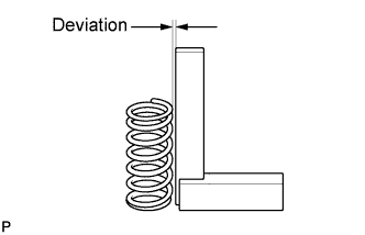
Using a steel square, measure the deviation of the inner compression spring.
- Maximum deviation:
- 1.5 mm (0.059 in.)
- Maximum angle (reference):
- 2°
 |
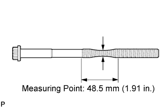
| 13. INSPECT CYLINDER HEAD SET BOLT |
Using a vernier caliper, measure the minimum diameter of the elongated thread at the measuring point.
- Standard outside diameter:
- 11.8 to 12.0 mm (0.465 to 0.472 in.)
- Minimum outside diameter:
- 11.20 mm (0.4409 in.)
 |