Система Sfi Цепь Контрольной Лампы Неисправности Mil. Corolla Auris
Двигатель. COROLLA, AURIS. ZZE150 ZRE151,152 NDE150
DESCRIPTION
WIRING DIAGRAM
INSPECTION PROCEDURE
CHECK THAT MIL IS ILLUMINATED
CHECK WHETHER MIL TURNS OFF
CHECK HARNESS AND CONNECTOR (CHECK FOR SHORT IN WIRE HARNESS)
CHECK HARNESS AND CONNECTOR (COMBINATION METER - ECM)
CHECK THAT ENGINE STARTS
CHECK COMBINATION METER ASSEMBLY (COMBINATION METER - BODY GROUND)
CHECK HARNESS AND CONNECTOR (COMBINATION METER - ECM)
СИСТЕМА SFI - Цепь контрольной лампы неисправности MIL |
DESCRIPTION
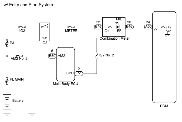
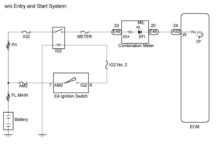
The MIL (Malfunction Indicator Lamp) is used to indicate vehicle malfunction detected by the ECM. When the ignition switch is turned on (IG), power is supplied to the MIL circuit, and the ECM provides the circuit ground which illuminates the MIL.The MIL operation can be checked visually: When the ignition switch is first turned on (IG), the MIL should be illuminated and should then turn off. If the MIL remains illuminated or is not illuminated, conduct the following troubleshooting procedure using the intelligent tester.
WIRING DIAGRAM
INSPECTION PROCEDURE
| 1.CHECK THAT MIL IS ILLUMINATED |
Turn the ignition switch on (IG).
Check the illumination of the MIL.
- Result:
Condition
| Proceed to
|
MIL remains illuminated (Even after ignition switch on (IG) and several seconds have passed, MIL still remains illuminated)
| A
|
MIL remains off (Does not illuminate at all)
| B
|
MIL illuminates for several seconds, but turns off after engine is started
| C
|
| 2.CHECK WHETHER MIL TURNS OFF |
Connect the intelligent tester to the DLC3.
Turn the ignition switch on (IG).
Turn the tester on.
Select the following menu items: Powertrain / Engine and ECT / DTC.
Check if any DTCs have been stored. Note down any DTCs.
Clear the DTCs (See page Нажмите здесь).
Check if the MIL goes off.
- OK:
- MIL goes off.
| 3.CHECK HARNESS AND CONNECTOR (CHECK FOR SHORT IN WIRE HARNESS) |
Disconnect the ECM connector.
Turn the ignition switch on (IG).
Check that the MIL is not illuminated.
- OK:
- MIL is not illuminated.
Reconnect the ECM connector.
| 4.CHECK HARNESS AND CONNECTOR (COMBINATION METER - ECM) |
Disconnect the combination meter connector.
Disconnect the ECM connector.
Measure the resistance according to the value(s) in the table below.
- Standard resistance (Check for short):
Tester Connection
| Condition
| Specified Condition
|
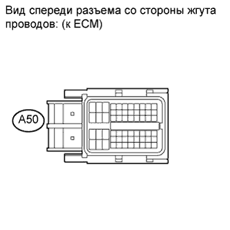
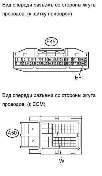
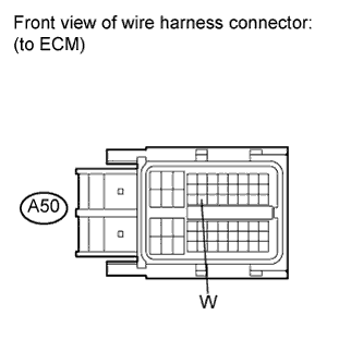
E46-20 (EFI) or A50-24 (W) - Body ground
| Always
| 10 kΩ or higher
|
Reconnect the combination meter connector.
Reconnect the ECM connector.
- Result:
Result
| Proceed to
|
NG
| A
|
OK (for Hatchback)
| B
|
OK (for Sedan)
| C
|
| A |
|
|
|
| REPAIR OR REPLACE HARNESS OR CONNECTOR (COMBINATION METER - ECM) |
|
| 5.CHECK THAT ENGINE STARTS |
Turn the ignition switch on (IG).
Start the engine.
- Result:
Result
| Proceed to
|
Engine starts
| A
|
Engine does not start*
| B
|
- УКАЗАНИЕ:
- *: The intelligent tester cannot communicate with the ECM.
| 6.CHECK COMBINATION METER ASSEMBLY (COMBINATION METER - BODY GROUND) |
Disconnect the ECM connector.
Turn the ignition switch on (IG).
Measure the voltage according to the value(s) in the table below.
- Standard voltage:
Tester Connection
| Condition
| Specified Condition
|
A50-24 (W) - Body ground
| Ignition switch on (IG)
| 9 to 14 V
|
| 7.CHECK HARNESS AND CONNECTOR (COMBINATION METER - ECM) |
Disconnect the combination meter connector.
Disconnect the ECM connector.
Measure the resistance according to the value(s) in the table below.
- Standard resistance (Check for open):
Tester Connection
| Condition
| Specified Condition
|
E46-20 (EFI) - A50-24 (W)
| Always
| Below 1 Ω
|
Reconnect the ECM connector.
Reconnect the combination meter connector.
- Result:
Result
| Proceed to
|
NG
| A
|
OK (for Hatchback)
| B
|
OK (for Sedan)
| C
|
| A |
|
|
|
| REPAIR OR REPLACE HARNESS OR CONNECTOR (COMBINATION METER - ECM) |
|