Двигатель. COROLLA, AURIS. ZZE150 ZRE151,152 NDE150
DESCRIPTION
WIRING DIAGRAM
INSPECTION PROCEDURE
CHECK ANY OTHER DTCS OUTPUT (IN ADDITION TO DTC P0234 AND/OR P0299)
CHECK VACUUM HOSE CONNECTIONS
CHECK VACUUM HOSES (CHECK VACUUM BETWEEN TURBOCHARGER - VRV FOR TURBO CHARGER)
INSPECT VACUUM REGULATING VALVE ASSEMBLY (OPERATION)
INSPECT VACUUM REGULATING VALVE ASSEMBLY (RESISTANCE)
CHECK HARNESS AND CONNECTOR (VACUUM REGULATING VALVE - ECM)
READ VALUE USING INTELLIGENT TESTER (MANIFOLD ABSOLUTE PRESSURE)
INSPECT DIESEL THROTTLE BODY ASSEMBLY (INTAKE SHUTTER)
CHECK HARNESS AND CONNECTOR (DIESEL THROTTLE BODY ASSEMBLY - ECM)
INSPECT EGR VALVE ASSEMBLY
CHECK HARNESS AND CONNECTOR (EGR VALVE ASSEMBLY - ECM)
INSPECT ECM (EGR VOLTAGE)
CHECK FOR DEPOSIT (EGR VALVE ASSEMBLY)
CHECK FOR DEPOSIT (EGR PASSAGE)
INSPECT FOR EXHAUST GAS LEAK
CHECK HARNESS AND CONNECTOR (MANIFOLD ABSOLUTE PRESSURE SENSOR - ECM)
DTC P0234 Turbocharger / Supercharger Overboost Condition |
DTC P0299 Turbocharger / Supercharger Underboost |
DESCRIPTION
Refer to DTC P0045 (See page Нажмите здесь).DTC No.
| DTC Detection Condition
| Trouble Area
|
P0234
| Actual turbocharger pressure is higher than target pressure for about 10 seconds
(The MIL is illuminated and a DTC is immediately set when a malfunction is detected)
| - Vacuum regulating valve
- Open or short in vacuum regulating valve circuit
- Turbocharger assembly
- EGR valve assembly
- Diesel throttle body assembly (intake shutter)
- Manifold absolute pressure sensor
- Vacuum hose
- ECM
|
P0299
| Actual turbocharger pressure is lower than target pressure for about 10 seconds
(The MIL is illuminated and a DTC is immediately set when a malfunction is detected)
|
- УКАЗАНИЕ:
- These DTCs are set during steady speed driving with a high engine load (at an engine speed of 3000 rpm or more).
WIRING DIAGRAM
Refer to DTC P0045 for vacuum regulating valve circuit (See page Нажмите здесь).Refer to DTC P0236 for manifold absolute pressure sensor circuit (See page Нажмите здесь).Refer to DTC P0400 for EGR valve circuit (See page Нажмите здесь).
INSPECTION PROCEDURE
- УКАЗАНИЕ:
- Read freeze frame data using an intelligent tester. The ECM records vehicle and driving condition information as freeze frame data the moment a DTC is stored. When troubleshooting, freeze frame data can be helpful in determining whether the vehicle was running or stopped, whether the engine was warmed up or not, whether the air fuel ratio was lean or rich, as well as other data recorded at the time of a malfunction.
| 1.CHECK ANY OTHER DTCS OUTPUT (IN ADDITION TO DTC P0234 AND/OR P0299) |
Connect the intelligent tester to the DLC3.
Turn the ignition switch to the ON position.
Turn the tester on.
Enter the following menu items: Powertrain / Engine and ECT / DTC.
Read the DTCs.
- Result:
Result
| Proceed to
|
DTC P0234 and/or P0299 are output
| A
|
DTC P0234 and/or P0299 and other DTCs are output
| B
|
| 2.CHECK VACUUM HOSE CONNECTIONS |
- УКАЗАНИЕ:
- Check the vacuum hose connection of the turbocharger system.
- OK:
- The vacuum hoses are appropriately connected to each other.
| | REPAIR OR REPLACE VACUUM HOSES |
|
|
| 3.CHECK VACUUM HOSES (CHECK VACUUM BETWEEN TURBOCHARGER - VRV FOR TURBO CHARGER) |
Using a three-way connector, connect a vacuum gauge to the hoses between the vacuum regulating valve and turbocharger.
Warm up the engine coolant temperature to more than 75°C (167°F).
Check the vacuum at an idling speed.
- Result:
Result
| Proceed to
|
0 kPa (0 mmHg, 0 in.Hg) to 50 kPa (375 mmHg, 14.8 in.Hg)
| A
|
Above 50 kPa (375 mmHg, 14.8 in.Hg)
| B
|
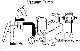
| 4.INSPECT VACUUM REGULATING VALVE ASSEMBLY (OPERATION) |
Remove the vacuum regulating valve (See page Нажмите здесь).
Apply 4 dry batteries of 1.5 V in series.
Check that the needle does not move when a vacuum is applied to the vacuum inlet port.
- OK:
- The vacuum regulating valve operates normally.
Reinstall the vacuum regulating valve (See page Нажмите здесь).
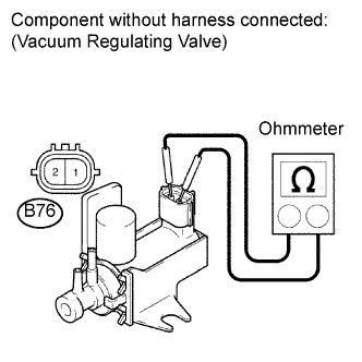
| 5.INSPECT VACUUM REGULATING VALVE ASSEMBLY (RESISTANCE) |
Remove the vacuum regulating valve (See page Нажмите здесь).
Measure the resistance according to the value(s) in the table below.
- Standard resistance:
Tester Connection
| Condition
| Specified Condition
|
B76-1 - B76-2
| 20°C (68°F)
| 11 to 13 Ω
|
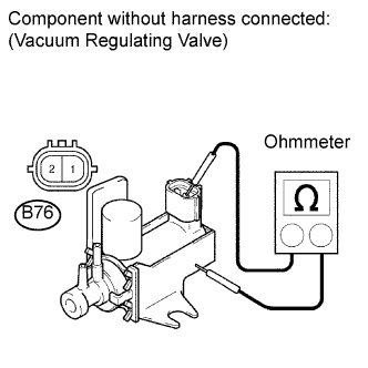
Measure the resistance according to the value(s) in the table below.
- Standard resistance:
Tester Connection
| Condition
| Specified Condition
|
B76-1 - Body
| Always
| 10 kΩ or higher
|
B76-2 - Body
| Always
| 10 kΩ or higher
|
Reinstall the vacuum regulating valve (See page Нажмите здесь).
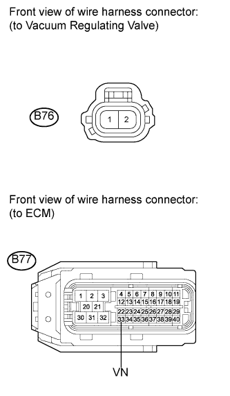
| 6.CHECK HARNESS AND CONNECTOR (VACUUM REGULATING VALVE - ECM) |
Disconnect the vacuum regulating valve connector.
Disconnect the ECM connector.
Measure the resistance according to the value(s) in the table below.
- Standard resistance (check for open):
Tester Connection
| Condition
| Specified Condition
|
B76-2 - B77-33 (VN)
| Always
| Below 1 Ω
|
- Standard resistance (check for short):
Tester Connection
| Condition
| Specified Condition
|
B76-2 or B77-33 (VN) - Body ground
| Always
| 10 kΩ or higher
|
Reconnect the vacuum regulating valve connector.
Reconnect the ECM connector.
| | REPAIR OR REPLACE HARNESS OR CONNECTOR (VACUUM REGULATING VALVE - ECM) |
|
|
| 7.READ VALUE USING INTELLIGENT TESTER (MANIFOLD ABSOLUTE PRESSURE) |
Connect the intelligent tester to the DLC3.
Turn the ignition switch to the ON position.
Turn the tester on.
Enter the following menu items: Powertrain / Engine and ECT / Data List / PIM.
Read the values.
- OK:
- Same value as the actual atmospheric pressure.
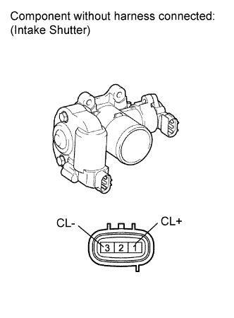
| 8.INSPECT DIESEL THROTTLE BODY ASSEMBLY (INTAKE SHUTTER) |
Disconnect the diesel throttle body assembly connector.
Measure the resistance according to the value(s) in the table below.
- Standard resistance:
Tester Connection
| Condition
| Specified Condition
|
1 (CL+) - 3 (CL-)
| 20°C (68°F)
| 0.3 to 100 Ω
|
Reconnect the diesel throttle body assembly connector.
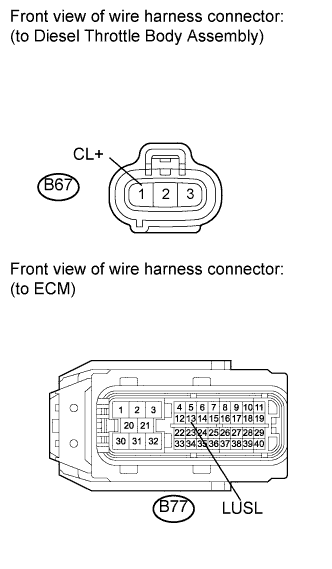
| 9.CHECK HARNESS AND CONNECTOR (DIESEL THROTTLE BODY ASSEMBLY - ECM) |
Disconnect the diesel throttle body assembly connector.
Disconnect the ECM connector.
Measure the resistance according to the value(s) in the table below.
- Standard resistance (Check for open):
Tester Connections
| Condition
| Specified Condition
|
B67-1 (CL+) - B77-13 (LUSL)
| Always
| Below 1 Ω
|
- Standard resistance (Check for short):
Tester Connection
| Condition
| Specified Condition
|
B67-1 (CL+) or B77-13 (LUSL) - Body ground
| Always
| 10 kΩ or higher
|
Reconnect the diesel throttle body assembly connector.
Reconnect the ECM connector.
| | REPAIR OR REPLACE HARNESS OR CONNECTOR (DIESEL THROTTLE BODY ASSEMBLY - ECM) |
|
|
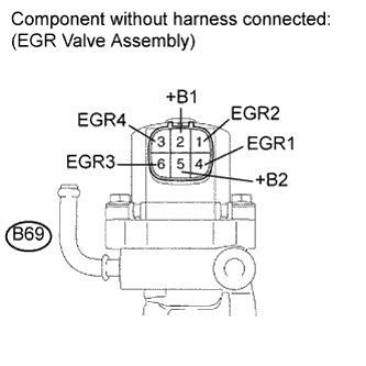
| 10.INSPECT EGR VALVE ASSEMBLY |
Disconnect EGR valve assembly connector.
Measure the resistance according to the value(s) in the table below.
- Standard resistance:
Tester Connection
| Condition
| Specified Condition
|
B69-5 (+B2) - B69-4 (EGR1)
| 20°C (68°F)
| 18.2 to 21.0 Ω
|
B69-5 (+B2) - B69-6 (EGR3)
| 20°C (68°F)
| 18.2 to 21.0 Ω
|
B69-2 (+B1) - B69-1 (EGR2)
| 20°C (68°F)
| 18.2 to 21.0 Ω
|
B69-2 (+B1) - B69-3 (EGR4)
| 20°C (68°F)
| 18.2 to 21.0 Ω
|
Reconnect the EGR valve assembly assembly.
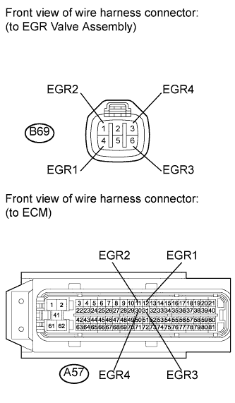
| 11.CHECK HARNESS AND CONNECTOR (EGR VALVE ASSEMBLY - ECM) |
Disconnect the EGR valve assembly connector.
Disconnect the ECM connector.
Measure the resistance according to the value(s) in the table below.
- Standard resistance (Check for open):
Tester Connection
| Condition
| Specified Condition
|
B69-4 (EGR1) - A57-12 (EGR1)
| Always
| Below 1 Ω
|
B69-1 (EGR2) - A57-11 (EGR2)
| Always
| Below 1 Ω
|
B69-6 (EGR3) - A57-31 (EGR3)
| Always
| Below 1 Ω
|
B69-3 (EGR4) - A57-30 (EGR4)
| Always
| Below 1 Ω
|
- Standard resistance (Check for short):
Tester Connection
| Condition
| Specified Condition
|
B69-4 (EGR1) or A57-12 (EGR1) - Body ground
| Always
| 10 kΩ or higher
|
B69-1 (EGR2) or A57-11 (EGR2) - Body ground
| Always
| 10 kΩ or higher
|
B69-6 (EGR3) or A57-31 (EGR3) - Body ground
| Always
| 10 kΩ or higher
|
B69-3 (EGR4) or A57-30 (EGR4) - Body ground
| Always
| 10 kΩ or higher
|
Reconnect the EGR valve assembly connector.
Reconnect the ECM connector.
| | REPAIR OR REPLACE HARNESS OR CONNECTOR (EGR VALVE ASSEMBLY - ECM) |
|
|
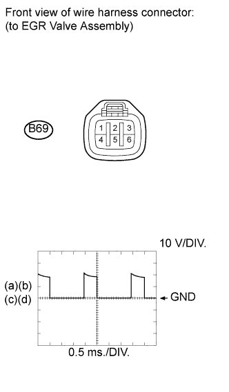
| 12.INSPECT ECM (EGR VOLTAGE) |
Disconnect the EGR valve assembly connector.
Inspect the ECM using an oscilloscope.
While repeating quick engine RPM accelerations, check the waveform between the terminals of the EGR valve connector.
- Standard:
Tester Connection
| Condition
| Specified Condition
|
B69-4 (EGR1) - Body ground
| Repeat quick engine RPM accelerations
| Correct waveform shown
|
B69-1 (EGR2) - Body ground
| Repeat quick engine RPM accelerations
|
B69-6 (EGR3) - Body ground
| Repeat quick engine RPM accelerations
|
B69-3 (EGR4) - Body ground
| Repeat quick engine RPM accelerations
|
Reconnect the EGR valve assembly connector.
| 13.CHECK FOR DEPOSIT (EGR VALVE ASSEMBLY) |
- OK:
- No deposit
| | REMOVE FOREIGN OBJECT AND CLEAN EGR VALVE ASSEMBLY (Нажмите здесь) |
|
|
| 14.CHECK FOR DEPOSIT (EGR PASSAGE) |
- OK:
- No deposit
| | REPAIR OR REPLACE MALFUNCTIONING PARTS, COMPONENT AND AREA (Нажмите здесь) |
|
|
| 15.INSPECT FOR EXHAUST GAS LEAK |
Check for exhaust gas leaks (See page Нажмите здесь).
- OK:
- No leakage
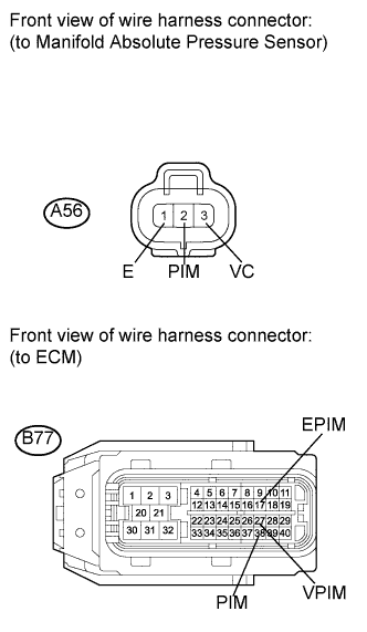
| 16.CHECK HARNESS AND CONNECTOR (MANIFOLD ABSOLUTE PRESSURE SENSOR - ECM) |
Disconnect the manifold absolute pressure sensor connector.
Disconnect the ECM connector.
Measure the resistance according to the value(s) in the table below.
- Standard resistance (check for open):
Tester Connection
| Condition
| Specified Condition
|
A56-2 (PIM) - B77-38 (PIM)
| Always
| Below 1 Ω
|
A56-3 (VC) - B77-27 (VPIM)
| Always
| Below 1 Ω
|
A56-1 (E) - B77-17 (EPIM)
| Always
| Below 1 Ω
|
- Standard resistance (check for short):
Tester Connection
| Condition
| Specified Condition
|
A56-2 (PIM) or B77-38 (PIM) - Body ground
| Always
| 10 kΩ or higher
|
A56-3 (VC) - B77-27 (VPIM) - Body ground
| Always
| 10 kΩ or higher
|
A56-1 (E) or B77-17 (EPIM) - Body ground
| Always
| 10 kΩ or higher
|
Reconnect the manifold absolute pressure sensor connector.
Reconnect the ECM connector.
| | REPAIR OR REPLACE HARNESS OR CONNECTOR (MANIFOLD ABSOLUTE PRESSURE SENSOR - ECM) |
|
|
| OK |
|
|
|
| REPLACE MANIFOLD ABSOLUTE PRESSURE SENSOR |
|