Dtc P1520 Stop Light Switch Circuit Malfunction. Corolla Auris
Двигатель. COROLLA, AURIS. ZZE150 ZRE151,152 NDE150
DESCRIPTION
WIRING DIAGRAM
INSPECTION PROCEDURE
CHECK STOP LIGHT SWITCH ASSEMBLY (TERMINAL VOLTAGE)
CHECK STOP LIGHT SWITCH ASSEMBLY (TERMINAL VOLTAGE)
INSPECT STOP LIGHT SWITCH ASSEMBLY
CHECK ECM (STP AND ST1 VOLTAGE)
INSPECT FUSE (STOP)
INSPECT FUSE (IGN FUSE)
CHECK HARNESS AND CONNECTOR (STOP LIGHT SWITCH ASSEMBLY - INTEGRATION RELAY (IG2 RELAY))
DTC P1520 Stop Light Switch Circuit Malfunction |
DESCRIPTION
In this system, the signal transmitted from the stop light switch is used to determine whether or not the brake system is normal.The stop light switch has a duplex system (signals STP and ST1-) to detect abnormalities. When the signals of depressing and releasing the brake pedal are detected simultaneously, the ECM interprets this as a malfunction of the stop light switch.- УКАЗАНИЕ:
- Normal condition is shown in the table below.
Signal
| Brake Pedal Released
| In Transition
| Brake Pedal Depressed
|
STP
| OFF
| ON
| ON
|
ST1-
| ON
| ON
| OFF
|
DTC No.
| DTC Detection Condition
| Trouble Area
|
P1520
| Conditions (a), (b) and (c) continue for 5.0 seconds or more:
(a) Ignition switch in the ON position
(b) Brake pedal depressed
(c) STP signal off when ST1- signal off
(The MIL is illuminated and a DTC is set when the same malfunction is detected on 2 consecutive trips*
*: One trip is counted when the ignition switch is turned from off to the ON position and back to off)
| - Short in stop light switch signal circuit
- Stop light switch
- ECM
|
- УКАЗАНИЕ:
- DTC P1520 is set when the ignition switch is in the ON position.
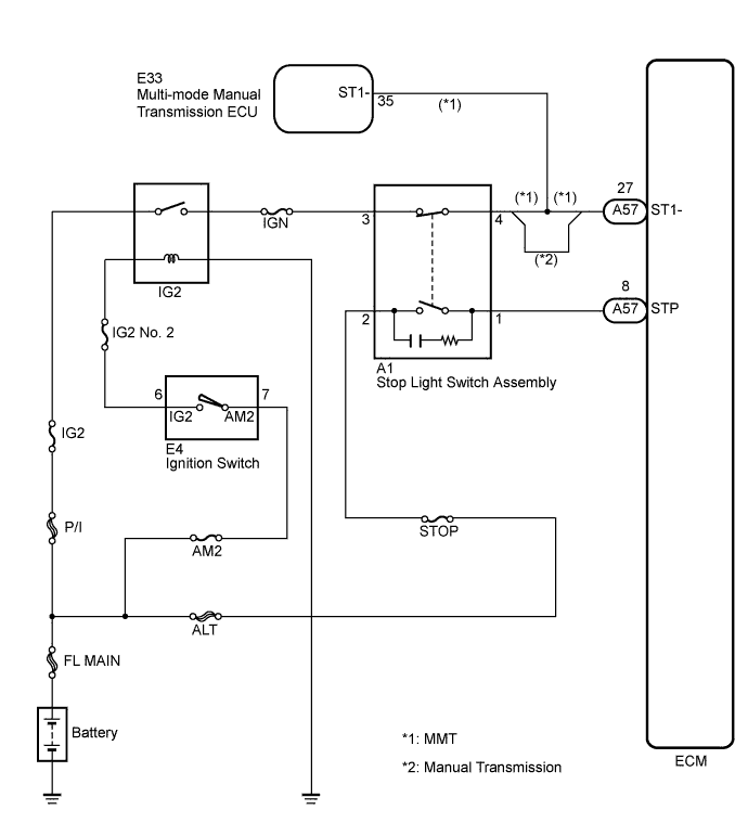
WIRING DIAGRAM
INSPECTION PROCEDURE
- УКАЗАНИЕ:
- Read freeze frame data using an intelligent tester. The ECM records vehicle and driving condition information as freeze frame data the moment a DTC is stored. When troubleshooting, freeze frame data can be helpful in determining whether the vehicle was running or stopped, whether the engine was warmed up or not, whether the air fuel ratio was lean or rich, as well as other data recorded at the time of a malfunction.
- STP signal conditions can be checked using an intelligent tester.
- Connect the intelligent tester to the DLC3.
- Turn the ignition switch to the ON position.
- Turn the tester on.
- Enter the following menu items: Powertrain / Engine and ECT / Data List / Stop Light SW.
- Check the STP signal when the brake pedal is depressed and released.
Brake Pedal Operation
| Specified Condition
|
Depressed
| STP signal ON
|
Released
| STP signal OFF
|
| 1.CHECK STOP LIGHT SWITCH ASSEMBLY (TERMINAL VOLTAGE) |
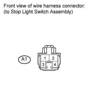
Disconnect the stop light switch assembly connector.
Measure the voltage according to the value(s) in the table below.
- Standard voltage:
Tester Connection
| Condition
| Specified Condition
|
A1-2 - Body ground
| Always
| 9 to 14 V
|
Reconnect the stop light switch assembly connector.
| 2.CHECK STOP LIGHT SWITCH ASSEMBLY (TERMINAL VOLTAGE) |
Disconnect the stop light switch assembly connector.
Turn the ignition switch to the ON position.
Measure the voltage according to the value(s) in the table below.
- Standard voltage:
Tester Connection
| Switch Condition
| Specified Condition
|
A1-3 - Body ground
| Ignition switch ON
| 9 to 14 V
|
Turn the ignition switch off.
Reconnect the stop light switch assembly connector.
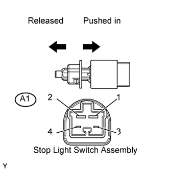
| 3.INSPECT STOP LIGHT SWITCH ASSEMBLY |
Remove the stop light switch assembly.
Measure the resistance according to the value(s) in the table below.
- Standard resistance:
Tester Connection
| Switch Position
| Specified Condition
|
1 - 2
| Switch pin released
| Below 1 Ω
|
Switch pin pushed in
| 10 kΩ or higher
|
3 - 4
| Switch pin released
| 10 kΩ or higher
|
Switch pin pushed in
| Below 1 Ω
|
Reinstall the stop light switch assembly.
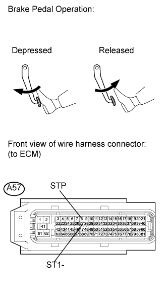
| 4.CHECK ECM (STP AND ST1 VOLTAGE) |
Disconnect the ECM connector.
Turn the ignition switch to the ON position.
Measure the voltage according to the value(s) in the table below.
- Standard voltage:
Tester Connection
| Brake control Operations
| Specified Condition
|
A57-27 (ST1-) - Body ground
| Released
| 9 to 14 V
|
Depressed
| 0 to 3 V
|
A57-8 (STP) - Body ground
| Released
| 0 to 3 V
|
Depressed
| 9 to 14 V
|
Reconnect the ECM connector.
| | REPAIR OR REPLACE HARNESS OR CONNECTOR (ECM - STOP LIGHT SWITCH ASSEMBLY) |
|
|
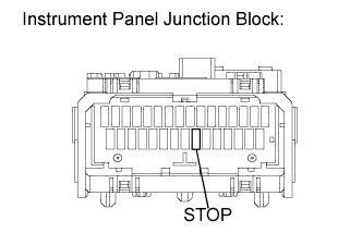
Remove the STOP fuse from the instrument panel junction block.
Measure the resistance according to the value(s) in the table below.
- Standard resistance:
Tester Connection
| Condition
| Specified Condition
|
STOP fuse
| Always
| Below 1 Ω
|
Reinstall the STOP fuse.
| OK |
|
|
|
| REPAIR OR REPLACE HARNESS OR CONNECTOR (STOP LIGHT SWITCH ASSEMBLY - BATTERY) |
|
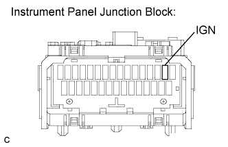
| 6.INSPECT FUSE (IGN FUSE) |
Remove the IGN fuse from the instrument panel junction block.
Measure the resistance according to the value(s) in the table below.
- Standard resistance:
Tester Connection
| Condition
| Specified Condition
|
IGN fuse
| Always
| Below 1 Ω
|
Reinstall the IGN fuse.
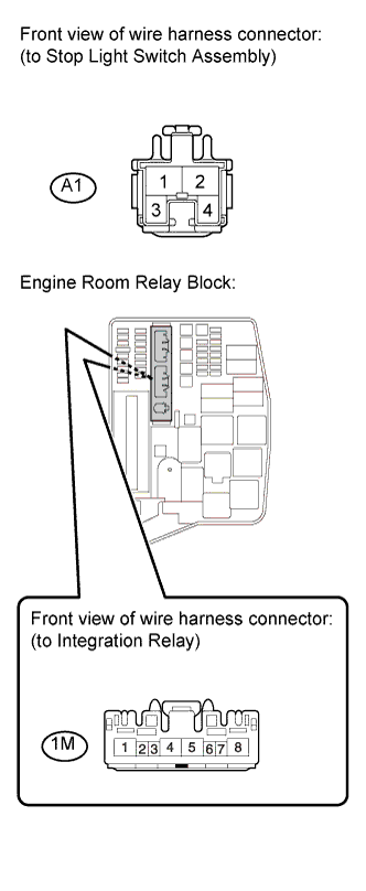
| 7.CHECK HARNESS AND CONNECTOR (STOP LIGHT SWITCH ASSEMBLY - INTEGRATION RELAY (IG2 RELAY)) |
Disconnect the stop light switch connector.
Remove the integration relay from the engine room relay block.
Measure the resistance according to the value(s) in the table below.
- Standard resistance (check for open):
Tester Connection
| Condition
| Specified Condition
|
A1-3 - 1M-4
| Always
| Below 1 Ω
|
- Standard resistance (check for short):
Tester Connection
| Condition
| Specified Condition
|
A1-3 or 1M-4 - Body ground
| Always
| 10 kΩ or higher
|
Reinstall the integration relay.
Reconnect the stop light switch connector.
| | REPAIR OR REPLACE HARNESS OR CONNECTOR (STOP LIGHT SWITCH ASSEMBLY - INTEGRATION RELAY (IG2 RELAY)) |
|
|