CHECK HARNESS AND CONNECTOR (DIESEL THROTTLE BODY ASSEMBLY - ECM)
REPLACE DIESEL THROTTLE BODY ASSEMBLY
CHECK WHETHER DTC OUTPUT RECURS (DTC P0122 AND/OR P0123)
DTC P0122 Throttle / Pedal Position Sensor / Switch "A" Circuit Low Input |
DTC P0123 Throttle / Pedal Position Sensor / Switch "A" Circuit High Input |
- УКАЗАНИЕ:
- These DTCs are related to the intake shutter (throttle valve) position sensor.
- This electronic throttle system does not use a throttle cable.
- This intake shutter position sensor is a non-contact type.
DESCRIPTION
The intake shutter (throttle valve) position sensor is mounted on the intake shutter body and it detects the opening angle of the intake shutter. This sensor is electronically controlled and uses Hall-effect elements.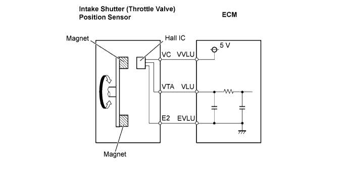
| DTC No. | DTC Detection Condition | Trouble Area |
| P0122 | Intake shutter position sensor output (VLU) is less than 0.2 V (The MIL is illuminated and a DTC is immediately set when a malfunction is detected) |
|
| P0123 | Intake shutter position sensor output (VLU) is more than 4.8 V (The MIL is illuminated and a DTC is immediately set when a malfunction is detected) |
|
- УКАЗАНИЕ:
- These DTCs are set when the ignition switch is in the ON position.
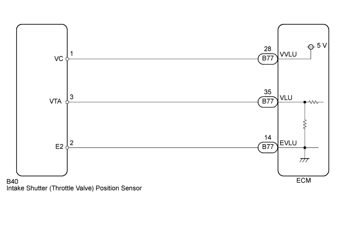
WIRING DIAGRAM
INSPECTION PROCEDURE
- УКАЗАНИЕ:
- Read freeze frame data using an intelligent tester. The ECM records vehicle and driving condition information as freeze frame data the moment a DTC is stored. When troubleshooting, freeze frame data can be helpful in determining whether the vehicle was running or stopped, whether the engine was warmed up or not, whether the air fuel ratio was lean or rich, as well as other data recorded at the time of a malfunction.
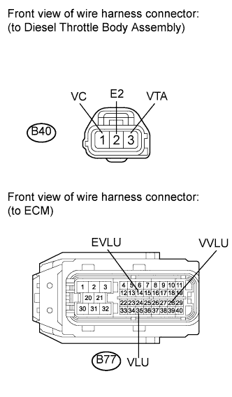
| 1.CHECK HARNESS AND CONNECTOR (DIESEL THROTTLE BODY ASSEMBLY - ECM) |
Disconnect the diesel throttle body assembly connector.
 |
Disconnect the ECM connector.
Measure the resistance according to the value(s) in the table below.
- Standard resistance (Check for open):
Tester Connection Condition Specified Condition B77-28 (VVLU) - B40-1 (VC) Always Below 1 Ω B77-35 (VLU) - B40-3 (VTA) Always Below 1 Ω B77-14 (EVLU) - B40-2 (E2) Always Below 1 Ω
- Standard resistance (Check for short):
Tester Connection Condition Specified Condition B77-28 (VVLU) or B40-1 (VC) - Body ground Always 10 kΩ or higher B77-35 (VLU) or B40-3 (VTA) - Body ground Always 10 kΩ or higher B77-14 (EVLU) or B40-2 (E2) - Body ground Always 10 kΩ or higher
Reconnect the diesel throttle body assembly connector.
Reconnect the ECM connector.
|
| ||||
| OK | |
| 2.INSPECT ECM (VC VOLTAGE) |
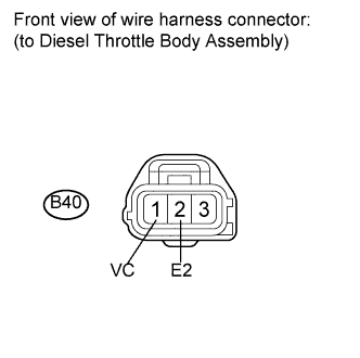
Disconnect the diesel throttle body assembly connector.
 |
Turn the ignition switch to the ON position.
Measure the voltage according to the value(s) in the table below.
- Standard voltage:
Tester Connection Switch Condition Specified Condition B40-1 (VC) - B40-2 (E2) Ignition switch ON 4.5 to 5.5 V
Reconnect the diesel throttle body assembly connector.
|
| ||||
| OK | |
| 3.REPLACE DIESEL THROTTLE BODY ASSEMBLY |
Replace diesel throttle body assembly (See page Нажмите здесь).
| NEXT | |
| 4.CHECK WHETHER DTC OUTPUT RECURS (DTC P0122 AND/OR P0123) |
Connect the intelligent tester to the DLC3.
Turn the ignition switch to the ON position.
Turn the tester on.
Enter the following menu items: Powertrain / Engine and ECT / DTC / Clear.
Clear the DTCs (See page Нажмите здесь).
Let the engine idle for 60 seconds, and repeat quick engine RPM accelerations (to 2500 rpm) for 30 seconds.
Enter the following menu items: Powertrain / Engine and ECT / DTC.
Read the DTCs.
- Result:
Result Proceed to DTC P0122 and/or P0123 are output A DTC is not output B
|
| ||||
| A | ||
| ||