Dtc P0380 Glow Plug / Heater Circuit A Malfunction. Corolla Auris
Двигатель. COROLLA, AURIS. ZZE150 ZRE151,152 NDE150
DESCRIPTION
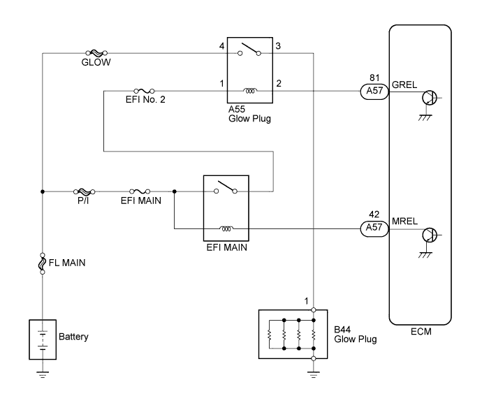
WIRING DIAGRAM
INSPECTION PROCEDURE
INSPECT GLOW PLUG RELAY ASSEMBLY
CHECK GLOW PLUG RELAY (VOLTAGE)
CHECK HARNESS AND CONNECTOR (GLOW PLUG RELAY - ECM)
CHECK FUSE (EFI NO. 2 FUSE)
DTC P0380 Glow Plug / Heater Circuit "A" Malfunction |
DESCRIPTION
The glow plug is mounted inside the engine combustion chamber. To ensure efficient engine starting with a cold engine, the ECM calculates the time interval the current needs to flow through the glow plug, depending on the starting engine coolant temperature when the ignition switch is turned to the ON position. The ECM then turns on the glow plug relay and permits the current to flow through the glow plug based on the ECM's calculated time. The glow plug is then heated, and enhances fuel combustion with a cold engine.DTC No.
| DTC Detection Condition
| Trouble Area
|
P0380
| When glow plug is turned from off to on, current does not flow through glow plug relay
(The MIL is illuminated and a DTC is set when the same malfunction is detected on 2 consecutive trips*
*: One trip is counted when the ignition switch is turned from off to the ON position and back to off)
| - Glow plug relay
- ECM
|
- УКАЗАНИЕ:
- DTC P0380 is set when the ignition switch is in the ON position after cold soak.
WIRING DIAGRAM
INSPECTION PROCEDURE
- УКАЗАНИЕ:
- Read freeze frame data using an intelligent tester. The ECM records vehicle and driving condition information as freeze frame data the moment a DTC is stored. When troubleshooting, freeze frame data can be helpful in determining whether the vehicle was running or stopped, whether the engine was warmed up or not, whether the air fuel ratio was lean or rich, as well as other data recorded at the time of a malfunction.
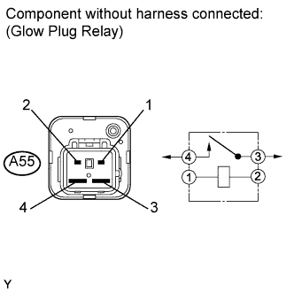
| 1.INSPECT GLOW PLUG RELAY ASSEMBLY |
Disconnect the glow plug relay connector.
Measure the resistance according to the value(s) in the table below.
- Standard resistance:
Tester Connection
| Condition
| Specified Condition
|
3 - 4
| When battery voltage not applied to terminals 1 and 2
| 10 kΩ or higher
|
3 - 4
| When battery voltage applied to terminals 1 and 2
| Below 1 Ω
|
Reinstall the glow plug relay connector.
| | REPLACE GLOW PLUG RELAY ASSEMBLY |
|
|
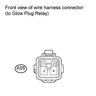
| 2.CHECK GLOW PLUG RELAY (VOLTAGE) |
Disconnect the glow plug relay connector.
Turn the ignition switch to the ON position.
Measure the voltage according to the value(s) in the table below.
- Standard voltage:
Tester Connection
| Switch Condition
| Specified Condition
|
A55-1 - Body ground
| Ignition switch ON
| 9 to 14 V
|
Reconnect the glow plug relay connector.
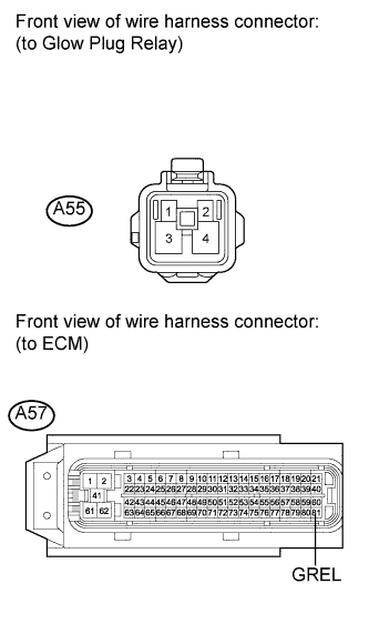
| 3.CHECK HARNESS AND CONNECTOR (GLOW PLUG RELAY - ECM) |
Disconnect the ECM connector.
Disconnect the glow plug relay connector.
Measure the resistance according to the value(s) in the table below.
- Standard resistance (check for open):
Tester Connection
| Condition
| Specified Condition
|
A55-2 - A57-81 (GREL)
| Always
| Below 1 Ω
|
- Standard resistance (check for short):
Tester Connection
| Condition
| Specified Condition
|
A55-2 or A57-81 (GREL) - Body ground
| Always
| 10 kΩ or higher
|
Reconnect the ECM connector.
Reconnect the glow plug relay connector.
| | REPAIR OR REPLACE HARNESS OR CONNECTOR (GLOW PLUG RELAY - ECM) |
|
|
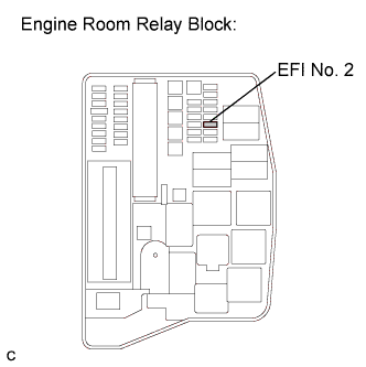
| 4.CHECK FUSE (EFI NO. 2 FUSE) |
Remove the EFI No. 2 fuse from the engine room relay block.
Measure the resistance according to the value(s) in the table below.
- Standard resistance:
Tester Connection
| Condition
| Specified Condition
|
EFI No. 2 fuse
| Always
| Below 1 Ω
|
Reinstall the EFI No. 2 fuse.
| | REPLACE FUSE (EFI NO. 2 FUSE) |
|
|
| OK |
|
|
|
| REPAIR OR REPLACE HARNESS OR CONNECTOR (GLOW PLUG RELAY - INTEGRATION RELAY (EFI MAIN RELAY)) |
|