DESCRIPTION
WIRING DIAGRAM
INSPECTION PROCEDURE
CHECK MIL CONDITION
CHECK IF MIL TURNS OFF
CHECK HARNESS AND CONNECTOR (FOR SHORT)
CHECK HARNESS AND CONNECTOR (ECM - COMBINATION METER ASSEMBLY)
CHECK IF MIL ILLUMINATES
INSPECT COMBINATION METER ASSEMBLY (MIL CIRCUIT)
СИСТЕМА ECD - MIL Circuit |
DESCRIPTION
The MIL is used to inform the user when the ECM has detected a vehicle malfunction.By turning the ignition switch to ON, power is supplied to the MIL circuit and the ECM provides the circuit ground that illuminates the MIL.Operation of the MIL should be checked visually: When the ignition switch is first turned to ON, the MIL should illuminate. When the engine is started, the MIL should turn off.
WIRING DIAGRAM
INSPECTION PROCEDURE
- ПРИМЕЧАНИЕ:
- Inspect the fuses for circuits related to this system before performing the following inspection procedure.
Check the MIL condition.
- Result:
Condition
| Proceed to
|
MIL remains on
| A
|
MIL does not illuminate
| B
|
Connect the intelligent tester to the DLC3.
Turn the ignition switch to ON and turn the tester on.
Check if DTCs have been stored (See page Нажмите здесь). If DTCs are stored, write them down.
Clear the DTCs using the intelligent tester (See page Нажмите здесь).
Check that the MIL turns off.
- OK:
- The MIL turns off.
| 3.CHECK HARNESS AND CONNECTOR (FOR SHORT) |
Disconnect the ECM connector.
Turn the ignition switch to ON.
Check that the MIL is not illuminated.
- OK:
- The MIL is not illuminated.
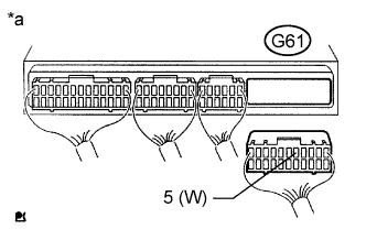
Text in Illustration*a
| Rear view of wire harness connector
(to ECM)
|
Reconnect the ECM connector.
| 4.CHECK HARNESS AND CONNECTOR (ECM - COMBINATION METER ASSEMBLY) |
Disconnect the ECM connector.
Disconnect the combination meter assembly connector.
Measure the resistance according to the value(s) in the table below.
- Standard Resistance (Check for Open):
Tester Connection
| Condition
| Specified Condition
|
G61-5 (W) - G7-7 (CHK)
| Always
| Below 1 Ω
|
- Standard Resistance (Check for Short):
Tester Connection
| Condition
| Specified Condition
|
G61-5 (W) or G7-7 (CHK) - Body ground
| Always
| 10 kΩ or higher
|
Reconnect the ECM connector.
Reconnect the combination meter assembly connector.
| | REPAIR OR REPLACE HARNESS OR CONNECTOR |
|
|
| 5.CHECK IF MIL ILLUMINATES |
Check that the MIL illuminates when turning the ignition switch to ON.
- OK:
- The MIL illuminates.
| 6.INSPECT COMBINATION METER ASSEMBLY (MIL CIRCUIT) |
Refer to the combination meter assembly troubleshooting procedures (See page Нажмите здесь).
| OK |
|
|
|
| REPAIR OR REPLACE HARNESS OR CONNECTOR (COMBINATION METER - ECM) |
|