Система Ecd Air Conditioning Cut Control Circuit
DESCRIPTION
WIRING DIAGRAM
INSPECTION PROCEDURE
When using intelligent tester:
READ VALUE USING INTELLIGENT TESTER (CHECK OPERATION OF AIR CONDITIONING CUT CONTROL)
INSPECT ECM (ACT VOLTAGE)
CHECK HARNESS AND CONNECTOR (ECM - AIR CONDITIONING AMPLIFIER)
When not using intelligent tester:
CHECK ECM (ACT VOLTAGE)
CHECK HARNESS AND CONNECTOR (ECM - AIR CONDITIONING AMPLIFIER)
СИСТЕМА ECD - Air Conditioning Cut Control Circuit |
DESCRIPTION
This circuit cuts air conditioning operation during vehicle acceleration in order to increase acceleration performance. During acceleration with the vehicle speed at 30 km/h (19 mph) or less and the accelerator pedal opening angle at 45° or more, the A/C magnetic switch is turned off for several seconds.The air conditioning is also controlled using the engine coolant temperature output from the ECM to the A/C amplifier.
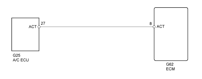
WIRING DIAGRAM
INSPECTION PROCEDURE
When using intelligent tester:
| 1.READ VALUE USING INTELLIGENT TESTER (CHECK OPERATION OF AIR CONDITIONING CUT CONTROL) |
Connect the intelligent tester to the DLC3.
Start the engine and turn the air conditioning switch on.
- УКАЗАНИЕ:
- The A/C magnetic clutch is turned on.
Enter the following menus: Powertrain / Engine and ECT / Active Test / A/C Cut SIG.
Check operation of the A/C magnetic clutch cut when air conditioning cut control is operated by the intelligent tester.
- OK:
- A/C magnetic clutch is turned off.
| OK |
|
|
|
| PROCEED TO NEXT SUSPECTED AREA SHOWN IN PROBLEM SYMPTOMS TABLE (Нажмите здесь) |
|
| 2.INSPECT ECM (ACT VOLTAGE) |
Start the engine.
Measure the voltage according to the value(s) in the table below.
- Standard Voltage:
Tester Connection
| Condition
| Specified Condition
|
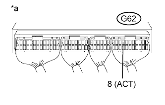
G62-8 (ACT) - Body ground
| Engine idling
| 11 to 14 V
|
G62-8 (ACT) - Body ground
| Ignition switch ON, engine stopped
| 0 to 3 V
|
Text in Illustration*a
| Component with harness connected
(ECM)
|
| 3.CHECK HARNESS AND CONNECTOR (ECM - AIR CONDITIONING AMPLIFIER) |
Disconnect the A/C amplifier connector.
Disconnect the ECM connector.
Measure the resistance according to the value(s) in the table below.
- Standard Resistance (Check for Open):
Tester Connection
| Condition
| Specified Condition
|
G25-27 (ACT) - G62-8 (ACT)
| Always
| Below 1 Ω
|
- Standard Resistance (Check for Short):
Tester Connection
| Condition
| Specified Condition
|
G25-27 (ACT) or G62-8 (ACT) - Body ground
| Always
| 10 kΩ or higher
|
Reconnect the A/C amplifier connector.
Reconnect the ECM connector.
| | REPAIR OR REPLACE HARNESS OR CONNECTOR |
|
|
When not using intelligent tester:
| 1.CHECK ECM (ACT VOLTAGE) |
Start the engine.
Measure the voltage according to the value(s) in the table below.
- Standard Voltage:
Tester Connection
| Condition
| Specified Condition
|
G62-8 (ACT) - Body ground
| Engine idling
| 11 to 14 V
|
G62-8 (ACT) - Body ground
| Ignition switch ON, engine stopped
| 0 to 3 V
|
Text in Illustration*a
| Component with harness connected
(ECM)
|
| 2.CHECK HARNESS AND CONNECTOR (ECM - AIR CONDITIONING AMPLIFIER) |
Disconnect the A/C amplifier connector.
Disconnect the ECM connector.
Measure the resistance according to the value(s) in the table below.
- Standard Resistance (Check for Open):
Tester Connection
| Condition
| Specified Condition
|
G25-27 (ACT) - G62-8 (ACT)
| Always
| Below 1 Ω
|
- Standard Resistance (Check for Short):
Tester Connection
| Condition
| Specified Condition
|
G25-27 (ACT) or G62-8 (ACT) - Body ground
| Always
| 10 kΩ or higher
|
Reconnect the A/C amplifier connector.
Reconnect the ECM connector.
| | REPAIR OR REPLACE HARNESS OR CONNECTOR |
|
|