INSPECT CYLINDER BLOCK FOR WARPAGE
INSPECT CYLINDER BORE
INSPECT PISTON
INSPECT PISTON OIL CLEARANCE
INSPECT RING GROOVE CLEARANCE
INSPECT PISTON RING END GAP
INSPECT PISTON PIN OIL CLEARANCE
INSPECT CONNECTING ROD SUB-ASSEMBLY
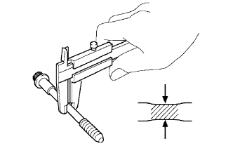
INSPECT CONNECTING ROD BOLT
INSPECT CRANKSHAFT
INSPECT CRANKSHAFT BEARING CAP SET BOLT
Engine Unit -- Inspection |
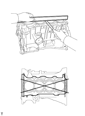
| 1. INSPECT CYLINDER BLOCK FOR WARPAGE |
Using a precision straightedge and feeler gauge, measure the warpage of the surface that is in contact with the cylinder head gasket.
- Maximum warpage:
- 0.05 mm (0.0020 in.)
If the warpage is greater than the maximum, replace the cylinder block.
Using a cylinder gauge, measure the cylinder bore diameter at positions A and B in the thrust and axial directions.
- Standard diameter:
- 88.500 to 88.513 mm (3.4843 to 3.4847 in.)
- Maximum diameter:
- 88.633 mm (3.4894 in.)
If the average diameter of the 4 positions is greater than the maximum, replace the cylinder block.
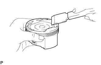
Using a gasket scraper, remove the carbon from the piston top.
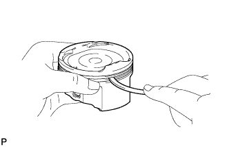
Using a groove cleaning tool or a broken ring, clean the piston ring grooves.
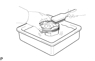
Using a brush and solvent, thoroughly clean the piston.
- ПРИМЕЧАНИЕ:
- Do not use a wire brush.
Using a micrometer, measure the piston diameter at right angles to the piston pin hole, and at the piston 44.3 mm (1.7587 in.) from the piston head.
- Standard piston diameter:
- 88.477 to 88.487 mm (3.5125 to 3.5129 in.)
If the diameter is not as specified, replace the piston.
| 4. INSPECT PISTON OIL CLEARANCE |
Subtract the piston diameter measurement from the cylinder bore diameter measurement.
- Standard oil clearance:
- 0.021 to 0.044 mm (0.0008 to 0.0017 in.)
- Maximum oil clearance:
- 0.10 mm (0.0039 in.)
If the oil clearance is greater than the maximum, replace all the pistons. If necessary, replace the cylinder block.
| 5. INSPECT RING GROOVE CLEARANCE |
Using a feeler gauge, measure the clearance between the new piston ring and wall of the ring groove.
- Standard ring groove clearance:
Item
| Specified Condition
|
No. 1 ring
| 0.020 to 0.070 mm (0.0008 to 0.0028 in.)
|
No. 2 ring
| 0.020 to 0.060 mm (0.0008 to 0.0024 in.)
|
Oil ring
| 0.020 to 0.070 mm (0.0008 to 0.0028 in.)
|
If the groove clearance is not as specified, replace the piston.
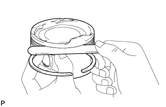
| 6. INSPECT PISTON RING END GAP |
Using a piston, push the piston ring a little beyond the bottom of the ring travel, 110 mm (4.33 in.) from the top of the cylinder block.
Using a feeler gauge, measure the end gap.
- Standard end gap:
Item
| Specified Condition
|
No. 1 ring
| 0.24 to 0.31 mm (0.0094 to 0.0122 in.)
|
No. 2 ring
| 0.33 to 0.43 mm (0.0130 to 0.0169 in.)
|
Oil ring
| 0.10 to 0.30 mm (0.0040 to 0.0119 in.)
|
- Maximum end gap:
Item
| Specified Condition
|
No. 1 ring
| 0.89 mm (0.0350 in.)
|
No. 2 ring
| 1.37 mm (0.0539 in.)
|
Oil ring
| 0.73 mm (0.0287 in.)
|
If the end gap is greater than the maximum, replace the piston ring. If the end gap is greater than the maximum, even with a new piston ring, replace the cylinder block.
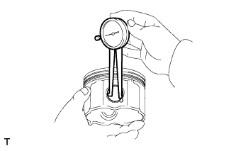
| 7. INSPECT PISTON PIN OIL CLEARANCE |
Using a caliper gauge, measure the piston pin bore diameter.
- Standard piston pin bore diameter:
- 22.001 to 22.010 mm (0.8662 to 0.8665 in.)
Item
| Specified Condition
|
A
| 22.001 to 22.004 mm (0.8662 to 0.8663 in.)
|
B
| 22.005 to 22.007 mm (0.8663 to 0.8664 in.)
|
C
| 22.008 to 22.010 mm (0.8665 to 0.8665 in.)
|
If the diameter is not as specified, replace the piston.
Using a micrometer, measure the piston pin diameter.
- Standard piston pin diameter:
- 21.997 to 22.006 mm (0.8660 to 0.8664 in.)
Item
| Specified Condition
|
A
| 21.997 to 22.000 mm (0.8660 to 0.8661 in.)
|
B
| 22.001 to 22.003 mm (0.8662 to 0.8663 in.)
|
C
| 22.004 to 22.006 mm (0.8663 to 0.8664 in.)
|
If the diameter is not as specified, replace the piston pin.
Using a caliper gauge, measure the connecting rod small end bore diameter.
- Standard connecting rod small end bore diameter:
- 22.005 to 22.014 mm (0.8663 to 0.8667 in.)
Item
| Specified Condition
|
A
| 22.005 to 22.008 mm (0.8663 to 0.8665 in.)
|
B
| 22.009 to 22.011 mm (0.8665 to 0.8666 in.)
|
C
| 22.012 to 22.014 mm (0.8666 to 0.8667 in.)
|
If the diameter is not as specified, replace the connecting rod.
Subtract the piston pin diameter measurement from the piston pin bore diameter measurement.
- Standard oil clearance:
- 0.001 to 0.007 mm (0.00004 to 0.0003 in.)
- Maximum oil clearance:
- 0.013 mm (0.0005 in.)
If the oil clearance is greater than the maximum, replace the connecting rod. If necessary, replace the piston and piston pin as a set.
Subtract the piston pin diameter measurement from the connecting rod small end bore diameter measurement.
- Standard oil clearance:
- 0.005 to 0.011 mm (0.0002 to 0.0004 in.)
- Maximum oil clearance:
- 0.017 mm (0.0007 in.)
If the oil clearance is greater than the maximum, replace the connecting rod. If necessary, replace the connecting rod and piston pin as a set.
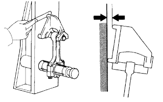
| 8. INSPECT CONNECTING ROD SUB-ASSEMBLY |
Using a connecting rod aligner and feeler gauge, check the connecting rod alignment.
Check for misalignment.
- Maximum misalignment:
- 0.05 mm (0.0020 in.) per 100 mm (3.94 in.)
If the misalignment is greater than the maximum, replace the connecting rod.
Check for twist.
- Maximum twist:
- 0.15 mm (0.0059 in.) per 100 mm (3.94 in.)
If the twist is greater than the maximum, replace the connecting rod.
| 9. INSPECT CONNECTING ROD BOLT |
Using vernier calipers, measure the tension portion diameter of the bolt.
- Standard diameter:
- 7.2 to 7.3 mm (0.283 to 0.287 in.)
- Minimum diameter:
- 7.0 mm (0.276 in.)
If the diameter is less than the minimum, replace the connecting rod bolt.
Using a dial indicator and V-blocks, measure the circle runout as shown in the illustration.
- Maximum taper and distortion:
- 0.003 mm (0.0001 in.)
If the taper and distortion are greater than the maximum, replace the crankshaft.
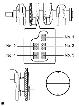
Using a micrometer, measure the diameter of each main journal.
- Standard diameter:
- 54.988 to 55.000 mm (2.1830 to 2.1654 in.)
If the diameter is not as specified, check the crankshaft oil clearance.
Check each main journal for taper and distortion as shown in the illustration.
- Maximum taper and distortion:
- 0.003 mm (0.0001 in.)
If the taper and distortion are greater than the maximum, replace the crankshaft.
- Standard diameter (Reference):
Mark
| Specified Condition
|
0
| 54.999 to 55.000 mm (2.1653 to 2.1654 in.)
|
1
| 54.997 to 54.998 mm (2.1652 to 2.1653 in.)
|
2
| 54.995 to 54.996 mm (2.1652 to 2.1652 in.)
|
3
| 54.993 to 54.994 mm (2.1651 to 2.1651 in.)
|
4
| 54.991 to 54.992 mm (2.1650 to 2.1650 in.)
|
5
| 54.998 to 54.990 mm (2.1649 to 2.1650 in.)
|
Using a micrometer, measure the diameter of each crank pin.
- Standard diameter:
- 47.990 to 48.000 mm (1.8894 to 1.8898 in.)
If the diameter is not as specified, check the connecting rod oil clearance.
Inspect each crank pin for taper and distortion as shown in the illustration.
- Maximum taper and distortion:
- 0.003 mm (0.0001 in.)
If the taper and distortion are greater than the maximum, replace the crankshaft.
| 11. INSPECT CRANKSHAFT BEARING CAP SET BOLT |
Using vernier calipers, measure the tension portion diameter of the bolts.
- Standard diameter:
- 7.5 to 7.6 mm (0.295 to 0.299 in.)
- Minimum diameter:
- 7.5 mm (0.295 in.)
If the diameter is less than the minimum, replace the bolt.