Engine Unit -- Inspection |
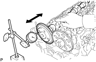
| 1. INSPECT CHAIN SUB-ASSEMBLY |
Using spring scale, pull the chain with a force of 147 N (15 kgf, 33 lbf) as shown in the illustration.
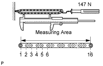 |
Using vernier calipers, measure the length of 16 links.
- Maximum chain elongation:
- 144.3 mm (5.681 in.)
- ПРИМЕЧАНИЕ:
- Perform the same measurement by pulling at random in 3 or more places to obtain an average.
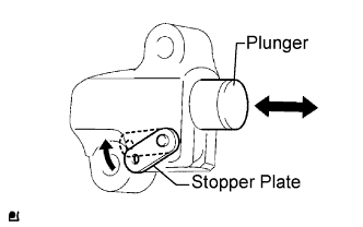
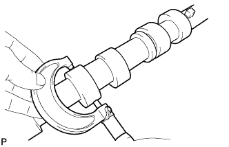
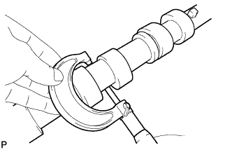
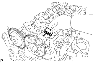
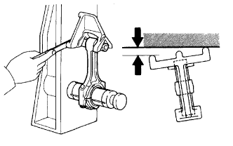
| 2. INSPECT NO. 1 CHAIN TENSIONER ASSEMBLY |
Move the stopper plate upward to release the lock. Push the plunger and check that it moves smoothly.
 |
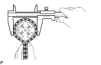
| 3. INSPECT CAMSHAFT TIMING SPROCKET |
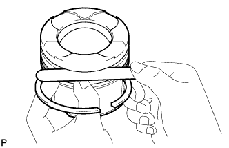
Wrap the chain around the sprocket.
Using vernier calipers, measure the sprocket diameter with the chain.
- Minimum sprocket with chain diameter:
- 132.6 mm (5.220 in.)
- УКАЗАНИЕ:
- The vernier calipers must contact the chain rollers for the measurement.
- If the diameter is less than the minimum, replace the chain and sprocket.
 |
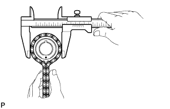
| 4. INSPECT CRANKSHAFT TIMING SPROCKET |
Wrap the chain around the drive sprocket.
Using vernier calipers, measure the sprocket diameter with the chain.
- Minimum sprocket with chain diameter:
- 69.1 mm (2.7017 in.)
- УКАЗАНИЕ:
- The vernier calipers must contact the chain rollers for the measurement.
 |
| 5. INSPECT CHAIN TENSIONER SLIPPER |
Using vernier calipers, measure the tensioner slipper wear.
- Maximum wear:
- 1.0 mm (0.039 in.)
| 6. INSPECT NO. 1 CHAIN VIBRATION DAMPER |
Using vernier calipers, measure the vibration damper wear.
- Maximum wear:
- 1.0 mm (0.039 in.)
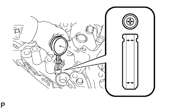
| 7. INSPECT VALVE LASH ADJUSTER ASSEMBLY |
- ПРИМЕЧАНИЕ:
- Keep the lash adjuster free from dirt and foreign objects.
- Use only clean engine oil.
Place the lash adjuster into a container full of new engine oil.
Insert the SST's tip into the lash adjuster's plunger and use the tip to press down on the checkball inside the plunger.
- Специальный инструмент (SST):
- 09276-75010
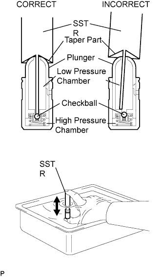 |
Squeeze the SST and lash adjuster together to move the plunger up and down 5 to 6 times.
Check the movement of the plunger and bleed the air.
- OK:
- Plunger moves up and down.
- ПРИМЕЧАНИЕ:
- When bleeding high-pressure air from the compression chamber, make sure that the tip of the SST is actually pressing the checkball as shown in the illustration. If the checkball is not pressed, air will not bleed.
After bleeding the air, remove the SST. Then try to quickly and firmly press the plunger by using the fingers.
- OK:
- Plunger is very difficult to move.
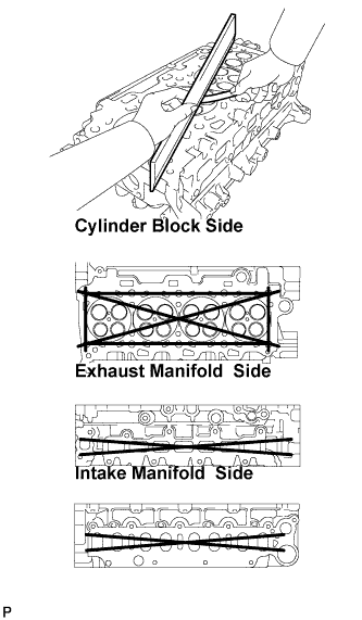
| 8. INSPECT CYLINDER HEAD SUB-ASSEMBLY |
Using a precision straightedge and feeler gauge, measure the warpage of the contact surface of the cylinder block and manifolds.
- Maximum warpage:
- 0.05 mm (0.0020 in.)
 |
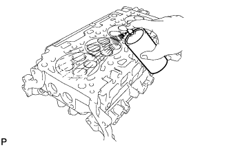
Using a dye penetrant, check the intake ports, exhaust ports and cylinder surface for cracks. If cracked, replace the cylinder head.
 |
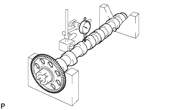
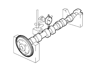
| 9. INSPECT CAMSHAFT |
Check the camshaft for runout.
Place the camshaft on V-blocks.
Using a dial indicator, measure the circle runout at the center journal.
- Maximum circle runout:
- 0.03 mm (0.0012 in.)
Using a micrometer, measure the cam lobe height.
- Standard cam lobe height:
- 37.559 to 37.759 mm (1.47870 to 1.48657 in.)
- Minimum cam lobe height:
- 37.559 mm (1.47870 in.)
 |
Using a micrometer, measure the journal diameter.
- Standard journal diameter:
- 26.969 to 26.985 mm (1.06117 to 1.06240 in.)
 |
| 10. INSPECT NO. 2 CAMSHAFT |
Check the camshaft for runout.
Place the camshaft on V-blocks.
Using a dial indicator, measure the circle runout at the center journal.
- Maximum circle runout:
- 0.03 mm (0.0012 in.)
Using a micrometer, measure the cam lobe height.
- Standard cam lobe height:
- 38.270 to 38.470 mm (1.50667 to 1.51456 in.)
- Minimum cam lobe height:
- 38.270 mm (1.50667 in.)
|
Using a micrometer, measure the journal diameter.
- Standard journal diameter:
- 26.969 to 26.985 mm (1.06117 to 1.06240 in.)
|
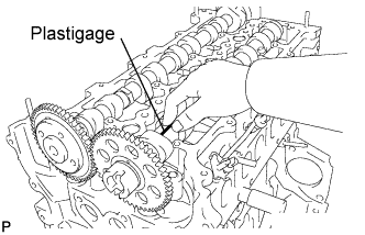
| 11. INSPECT CAMSHAFT OIL CLEARANCE |
Clean the bearing caps and camshaft journals.
Place the camshafts on the cylinder head.
Lay a strip of Plastigage across each of the camshaft journals.
 |
Install the bearing caps (see page RAV4_ACA30 RM0000019YC00AX_01_0034.html).
- ПРИМЕЧАНИЕ:
- Do not turn the camshaft.
Remove the bearing caps (see page RAV4_ACA30 RM0000019YB009X_01_0012.html).
Measure the Plastigage at its widest point.
- Standard journal clearance:
- 0.025 to 0.062 mm (0.00098 to 0.00244 in.)
- Maximum oil clearance:
- 0.062 mm (0.00244 in.)
 |
Completely remove the Plastigage.
| 12. INSPECT CAMSHAFT THRUST CLEARANCE |
Install the No. 2 camshaft and camshaft (see page RAV4_ACA30 RM0000019YC00AX_01_0034.html).
- Standard thrust clearance:
- 0.035 to 0.160 mm (0.00138 to 0.00630 in.)
- Maximum thrust clearance:
- 0.160 mm (0.00630 in.)
 |
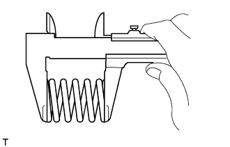
| 13. INSPECT COMPRESSION SPRING |
Using a vernier caliper, measure the free length of the compression spring.
- Free length:
- 45.90 mm (1.8071 in.)
 |
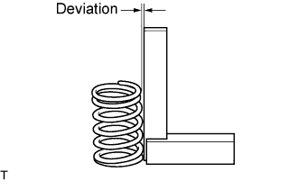
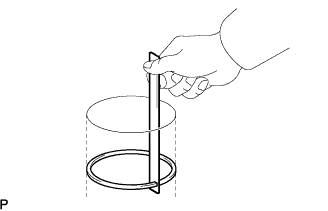
Using a steel square, measure the deviation of the inner compression spring.
- Maximum deviation:
- 1.5 mm (0.059 in.)
- Maximum angle (reference):
- 2°
 |
| 14. INSPECT INTAKE VALVE SEAT |
Apply a light coat of Prussian blue to the valve face.
Lightly press the valve face against the valve seat.
Check the valve face and valve seat by using the following procedure.
If Prussian blue appears around the entire valve face, the valve face is concentric. If not, replace the valve.
If Prussian blue appears around the entire valve seat, the guide and valve face are concentric. If not, resurface the valve seat.
Check that the valve seat contacts in the middle of the valve face with the width between 1.0 and 1.4 mm (0.039 and 0.055 in.).
| 15. INSPECT EXHAUST VALVE SEAT |
Apply a light coat of prussian blue to the valve face.
Lightly press the valve face against the valve seat.
Check the valve face and valve seat by using the following procedure.
If prussian blue appears around the entire valve face, the valve face is concentric. If not, replace the valve.
If prussian blue appears around the entire valve seat, the guide and valve face are concentric. If not, resurface the valve seat.
Check that the valve seat contacts in the middle of the valve face with the width between 1.0 and 1.4 mm (0.039 and 0.055 in.).
| 16. INSPECT INTAKE VALVE |
Using a gasket scraper, chip off any carbon from the valve head.
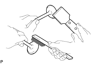 |
Using a wire brush, thoroughly clean the valve.
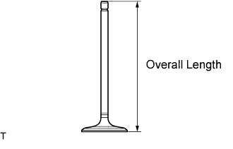
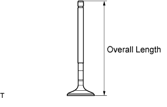
Using a vernier caliper, measure the valve's overall length.
- Standard overall length:
- 104.4 mm (4.110 in.)
- Minimum overall length:
- 104.1 mm (4.098 in.)
 |
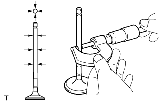
Using a micrometer, measure the diameter of the valve stem.
- Valve stem diameter:
- 5.970 to 5.985 mm (0.23504 to 0.23563 in.)
 |
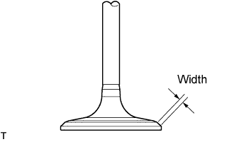
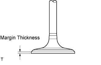
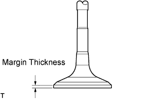
Using a vernier caliper, measure the valve head margin thickness.
- Standard margin thickness:
- 1.40 to 1.60 mm (0.055 to 0.063 in.)
- Minimum margin thickness:
- 0.50 mm (0.0197 in.)
 |
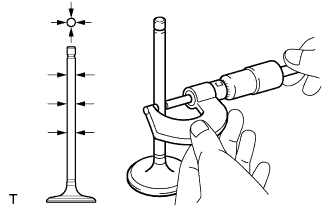
| 17. INSPECT EXHAUST VALVE |
Using a gasket scraper, chip off any carbon from the valve head.
|
Using a wire brush, thoroughly clean the valve.
Using a vernier caliper, measure the valve's overall length.
- Standard overall length:
- 104.1 mm (4.098 in.)
- Minimum overall length:
- 103.8 mm (4.087 in.)
 |
Using a micrometer, measure the diameter of the valve stem.
- Valve stem diameter:
- 5.960 to 5.975 mm (0.23465 to 0.23524 in.)
 |
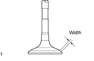
Using a vernier caliper, measure the valve head margin thickness.
- Standard margin thickness:
- 1.36 to 1.56 mm (0.0535 to 0.0614 in.)
- Minimum margin thickness:
- 0.50 mm (0.0197 in.)
 |
| 18. INSPECT VALVE GUIDE BUSH |
Using a caliper gauge, measure the inside diameter of the guide bush.
- Bush inside diameter:
- 6.010 to 6.030 mm (0.2366 to 0.2374 in.)
 |
Subtract the valve stem diameter measurement from the guide bush inside diameter measurement.
- Standard oil clearance:
Item Specified Condition Intake 0.025 to 0.060 mm (0.0010 to 0.0024 in.) Exhaust 0.035 to 0.070 mm (0.0014 to 0.0028 in.)
- Maximum oil clearance:
Item Specified Condition Intake 0.06 mm (0.0024 in.) Exhaust 0.07 mm (0.0028 in.)
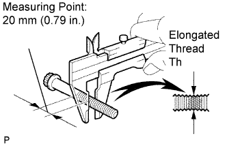
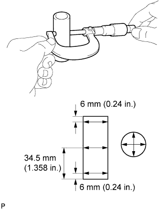
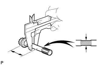
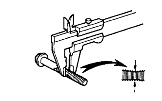
| 19. INSPECT CYLINDER HEAD SET BOLT |
Using a vernier caliper, measure the minimum diameter of the elongated thread at the measuring point.
- Standard outside diameter:
- 11.8 to 12.0 mm (0.465 to 0.472 in.)
- Minimum outside diameter:
- 11.20 mm (0.4409 in.)
- УКАЗАНИЕ:
- If a visual check reveals no excessively thin areas, check the center of the bolt (see illustration) and find the area that has the lowest diameter.
- If the diameter is less than the minimum, replace the cylinder head bolt.
 |
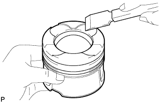
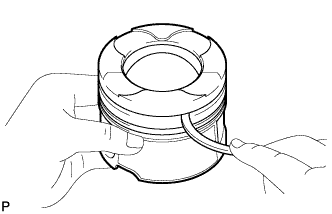
| 20. CLEAN PISTON |
Using a gasket scraper, remove the carbon from the piston top.
 |
Using a groove cleaning tool or broken ring, clean the piston ring grooves.
 |
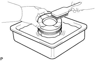
Using solvent and a brush, thoroughly clean the piston.
- ПРИМЕЧАНИЕ:
- Do not use a wire brush.
 |
| 21. INSPECT NO. 1 OIL NOZZLE SUB-ASSEMBLY |
Check the oil nozzles for damage or clogging.
If there is a damage or clogging, replace the oil nozzle.
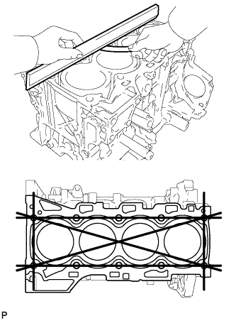
| 22. INSPECT CYLINDER BLOCK FOR WARPAGE |
Using a precision straightedge and feeler gauge, measure the warpage of the contact surface of the cylinder head gasket.
- Maximum warpage:
- 0.05 mm (0.0020 in.)
 |
Visually check the cylinder for vertical scratches.
If deep scratches are present, replace the cylinder block.
 |
| 23. INSPECT CYLINDER BORE |
Using a cylinder gauge, measure the cylinder bore diameter at positions A and B in the thrust and axial directions.
- Standard diameter:
- 86.000 to 86.013 mm (3.3858 to 3.3863 in.)
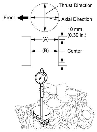 |
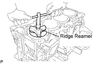
Inspect the cylinder ridge.
If the wear is less than 0.2 mm (0.008 in.), using a ridge reamer, grind the top of the cylinder.
 |
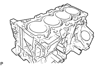
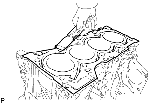
| 24. CLEAN CYLINDER BLOCK SUB-ASSEMBLY |
Using a gasket scraper, remove all the gasket material from the top surface of the cylinder block.
 |
Using a soft brush and solvent, thoroughly clean the cylinder block.
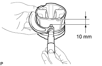
| 25. INSPECT PISTON DIAMETER |
Using a micrometer, measure the piston diameter at right angles to the piston center line where the distance from the bottom edge of the piston is as specified.
- Standard distance:
- 10 mm (0.39 in.)
- Standard piston diameter:
- 85.919 to 85.933 mm (3.3826 to 3.3831 in.)
 |
| 26. INSPECT PISTON OIL CLEARANCE |
Measure the cylinder bore diameter in the thrust direction.
Subtract the piston diameter measurement from the cylinder bore diameter measurement.
- Standard oil clearance:
- 0.067 to 0.094 mm (0.0026 to 0.0037 in.)
| 27. INSPECT RING GROOVE CLEARANCE |
Using a feeler gauge, measure the clearance between a new piston ring and the wall of the ring groove.
- Ring groove clearance:
Ring Specified Condition No. 1 0.11 to 0.15 mm (0.0043 to 0.0059 in.) No. 2 0.08 to 0.12 mm (0.0031 to 0.0047 in.) Oil 0.03 to 0.07 mm (0.0012 to 0.0028 in.)
 |
| 28. INSPECT PISTON RING END GAP |
Insert the piston ring into the cylinder bore.
Using a piston, push the piston ring a little beyond the bottom of the ring travel 110 mm (4.33 in.) from the top of the cylinder block.
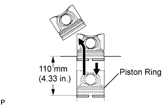 |
Using a feeler gauge, measure the end gap.
- Standard end gap:
Ring Specified Condition No. 1 0.22 to 0.32 mm (0.0087 to 0.0126 in.) No. 2 0.32 to 0.47 mm (0.0126 to 0.0185 in.) Oil 0.1 to 0.4 mm (0.0039 to 0.0157 in.)
- Maximum end gap:
Ring Specified Condition No. 1 0.32 mm (0.0126 in.) No. 2 0.47 mm (0.0185 in.) Oil 0.4 mm (0.0157 in.)
 |
| 29. INSPECT PISTON PIN OIL CLEARANCE |
Check each mark on the piston, piston pin and connecting rod.
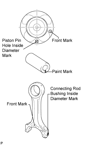 |
Using a caliper gauge, measure the inside diameter of the piston pin hole.
- Standard piston pin hole inside diameter:
Mark Specified Condition A 29.009 to 29.013 mm (1.14208 to 1.14224 in.) B 29.013 to 29.017 mm (1.14224 to 1.14240 in.) C 29.017 to 29.021 mm (1.14240 to 1.14256 in.)
 |
Using a micrometer, measure the piston pin diameter.
- Piston pin diameter:
Mark Specified Condition A (White) 29.000 to 29.004 mm (1.14173 to 1.14189 in.) B (Pink) 29.004 to 29.008 mm (1.14189 to 1.14204 in.) C (Blue) 29.008 to 29.012 mm (1.14204 to 1.14220 in.)
 |
Using a caliper gauge, measure the inside diameter of the connecting rod bush.
- Bush inside diameter:
Mark Specified Condition A 29.019 to 29.023 mm (1.14248 to 1.14264 in.) B 29.023 to 29.027 mm (1.14264 to 1.14279 in.) C 29.027 to 29.031 mm (1.14279 to 1.14295 in.)
 |
Subtract the piston pin diameter measurement from the piston pin hole diameter measurement.
- Standard oil clearance:
- 0.005 to 0.013 mm (0.00020 to 0.00051 in.)
- Maximum oil clearance:
- 0.05 mm (0.0020 in.)
Subtract the piston pin diameter measurement from the bush inside diameter measurement.
- Standard oil clearance:
- 0.015 to 0.023 mm (0.00059 to 0.00091 in.)
- Maximum oil clearance:
- 0.025 mm (0.0010 in.)
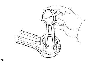
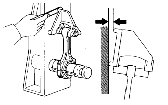
| 30. INSPECT CONNECTING ROD SUB-ASSEMBLY |
Using a rod aligner and feeler gauge, check the connecting rod alignment.
Check for bend.
- Maximum bend:
- 0.03 mm (0.0012 in.) per 100 mm (3.94 in.)
Check for twist.
- Maximum twist:
- 0.15 mm (0.0059 in.) per 100 mm (3.94 in.)
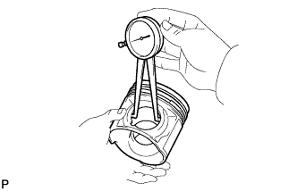
| 31. INSPECT CONNECTING ROD BOLT |
Using a vernier caliper, measure the tension portion diameter of the bolt.
- Standard diameter:
- 8.7 to 8.8 mm (0.343 to 0.346 in.)
- Minimum diameter:
- 8.5 mm (0.335 in.)
 |
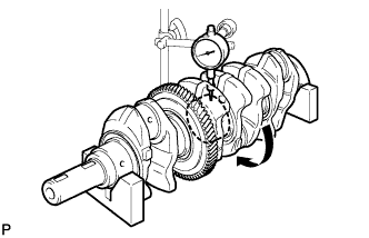
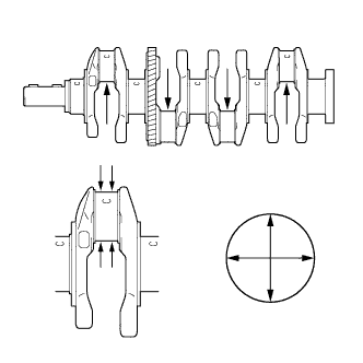
| 32. INSPECT CRANKSHAFT |
Inspect for circle runout.
Place the crankshaft on V-blocks.
Using a dial indicator, measure the circle runout at the center journal.
- Maximum circle runout:
- 0.04 mm (0.0015 in.)
Inspect the main journals.
Using a micrometer, measure the diameter of each main journal.
- Standard journal diameter:
- 59.000 to 59.018 mm (2.32283 to 2.32354 in.)
Check each main journal for taper and out-of- round as shown in the illustration.
- Maximum taper and out-of-round:
- 0.005 mm (0.0002 in.)
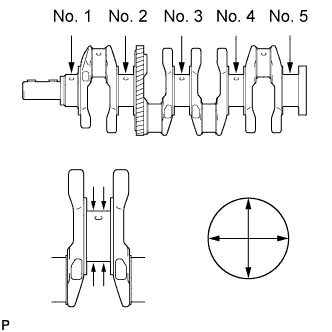
Inspect the crank pin.
Using a micrometer, measure the diameter of each crank pin.
- Diameter:
- 49.982 to 50.000 mm (1.96779 to 1.96850 in.)
Check each crank pin for taper and out-of-round as shown in the illustration.
- Maximum taper and out-of-round:
- 0.003 mm (0.0001 in.)
| 33. INSPECT CRANKSHAFT BEARING CAP SET BOLT |
Using a vernier caliper, measure the minimum diameter of the compressed thread at the measuring point.
- Standard diameter:
- 10.8 to 11.0 mm (0.425 to 0.433 in.)
- Minimum diameter:
- 10.4 mm (0.409 in.)
 |