DESCRIPTION
WIRING DIAGRAM
INSPECTION PROCEDURE
READ VALUE OF INTELLIGENT TESTER
INSPECT ECM (STSW TERMINAL VOLTAGE)
INSPECT ECM (STAR OUTPUT VOLTAGE)
INSPECT CLUTCH START SWITCH ASSEMBLY OR PARK / NEUTRAL POSITION SWITCH ASSEMBLY
CHECK HARNESS AND CONNECTOR (ECM - MAIN BODY ECU)
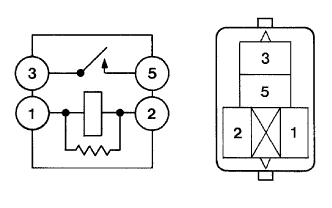
INSPECT ST CUT RELAY
INSPECT NO. 7 RELAY BLOCK (RELAY HOLDER TERMINAL VOLTAGE)
CHECK HARNESS AND CONNECTOR (ECM - CLUTCH START SWITCH OR PARK / NEUTRAL POSITION SWITCH ASSEMBLY - MAIN BODY ECU)
INSPECT NO. 7 RELAY BLOCK (CHECK FOR SHORT)
CHECK HARNESS AND CONNECTOR (CLUTCH START SWITCH OR PARK / NEUTRAL POSITION SWITCH ASSEMBLY - ECM - ST RELAY)
INSPECT BATTERY
CHECK BATTERY TERMINAL
SFI SYSTEM - Cranking Holding Function Circuit |
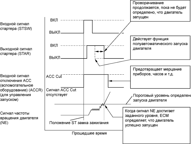
DESCRIPTION
The cranking holding control system keeps energizing the ST relay after the ECM detects the starter signal (STSW signal) from the main body ECU until the ECM performs a judgment of "Engine started". Furthermore, the ECM outputs an accessory cut signal (ACCR signal) to the ACC relay during cranking to prevent flickering of the combination meter, clock, audio system, and so on.When the ECM detects the STSW signal, the ECM outputs the starter relay drive signal (STAR signal) to the starter relay through the clutch start switch or park / neutral position switch, and then, the engine is cranked. When the ECM receives a stable engine speed signal (NE signal), more specifically, when the NE signal reaches a predetermined value, the ECM stops outputting the STAR signal. Also, the ECM monitors the ST relay operating conditions based on the STA terminal voltage status.
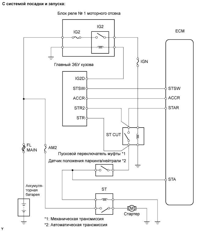
WIRING DIAGRAM
INSPECTION PROCEDURE
| 1.READ VALUE OF INTELLIGENT TESTER |
Connect the intelligent tester to the DLC3.
Turn the ignition switch on (IG) and turn the tester ON.
Select the following menu items: Powertrain / Engine and ECT / Data List / Starter Signal.
Check the result when the ignition switch is turned on (IG).
Check the result when the engine starts.
- Standard:
Ignition Switch Condition
| Tester Display (Starter Signal)
|
on (IG)
| OFF
|
Engine starts
| ON
|
| 2.INSPECT ECM (STSW TERMINAL VOLTAGE) |
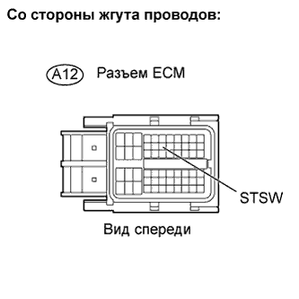
Disconnect the A12 ECM connector.
Depress the clutch pedal fully (for M/T models).
Shift lever is P position (for A/T models).
Measure the voltage between the ECM terminal and the body ground when operating the ignition switch to start cranking.
- Standard voltage:
Tester Connection
| Specified Condition
|
STSW (A12-14) - Body ground
| 10 to 14 V
|
Reconnect the ECM connector.
| 3.INSPECT ECM (STAR OUTPUT VOLTAGE) |
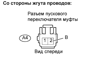
Disconnect the A4 clutch start switch connector (for M/T models).
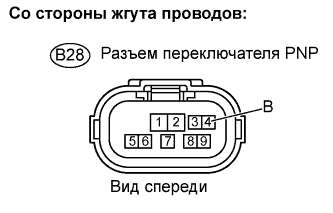
Disconnect the B28 Park / Neutral Position (PNP) switch connector (for A/T models)
Measure the voltage between the terminal of clutch start switch or PNP switch connector and the body ground while cranking the engine.
- Standard voltage:
M/TTester Connection
| Specified Condition
|
B (A4-2) - Body ground
| 10 to 14 V
|
- A/T:
Tester Connection
| Specified Condition
|
B (B28-4) - Body ground
| 10 to 14 V
|
Reconnect the clutch start switch connector.
Reconnect the PNP switch connector.
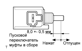
| 4.INSPECT CLUTCH START SWITCH ASSEMBLY OR PARK / NEUTRAL POSITION SWITCH ASSEMBLY |
M/T:
Disconnect the A4 clutch start switch connector.
Measure the resistance between the terminals of the clutch start switch assembly connector.
- Standard resistance:
Switch Condition
| Specified Condition
|
Pushed in
| Below 1 Ω
|
Released
| 10 kΩ or higher
|
A/T:
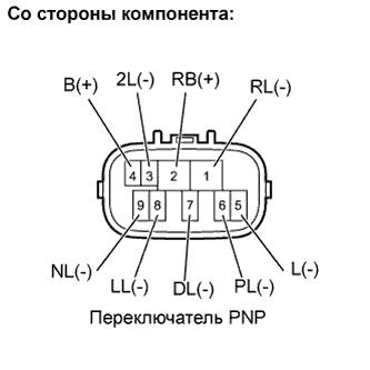
Disconnect the B28 PNP switch connector.
Measure the resistance between each terminal shown below when the shift lever is moved to each range.
- Standard resistance:
Shift Position
| Tester Connection
| Specified Condition
|
P
| PL (6) - RB (2)
| Below 1 Ω
|
L (5) - B (4)
|
R
| RL (1) - RB (2)
|
N
| NL (9) - RB (2)
|
L (5) - B (4)
|
D
| DL (7) - RB (2)
|
2
| 2L (3) - RB (2)
|
L
| LL (8) - RB (2)
|
| NG |
|
|
|
| REPLACE CLUTCH START SWITCH ASSEMBLY OR PARK / NEUTRAL POSITION SWITCH ASSEMBLY |
|
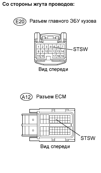
| 5.CHECK HARNESS AND CONNECTOR (ECM - MAIN BODY ECU) |
Disconnect the E20 main body ECU connector.
Disconnect the A12 ECM connector.
Measure the resistance.
- Standard resistance (Check for open):
Tester Connection
| Specified Condition
|
STSW (E20-4) - STSW (A12-14)
| Below 1 Ω
|
- Standard resistance (Check for short):
Tester Connection
| Specified Condition
|
STSW (E20-4) - Body ground
| Below 1 Ω
|
Reconnect the main body ECU connector.
Reconnect the ECM connector.
| | REPAIR OR REPLACE HARNESS OR CONNECTOR |
|
|
| OK |
|
|
|
| CHECK ENTRY AND START SYSTEM |
|
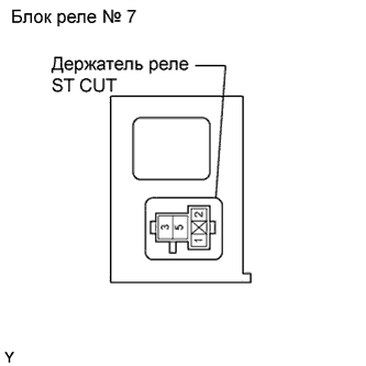
Remove the ST CUT relay from the No. 7 relay block.
Measure the resistance.
- Standard resistance:
Tester Connection
| Specified Condition
|
3 - 5
| 10 kΩ or higher
|
3 - 5
| Below 1 Ω
(When battery voltage applied to terminals 1 and 2)
|
Reinstall the relay.
| 7.INSPECT NO. 7 RELAY BLOCK (RELAY HOLDER TERMINAL VOLTAGE) |
Remove the ST CUT relay from the No. 7 relay block.
Turn the ignition switch on (IG).
Measure the voltage between the terminals of the ST CUT relay holder.
- Standard voltage:
Tester Connection
| Specified Condition
|
1 - 2
| 10 to 14 V
|
Reinstall the relay.
| | REPAIR OR REPLACE HARNESS OR CONNECTOR |
|
|
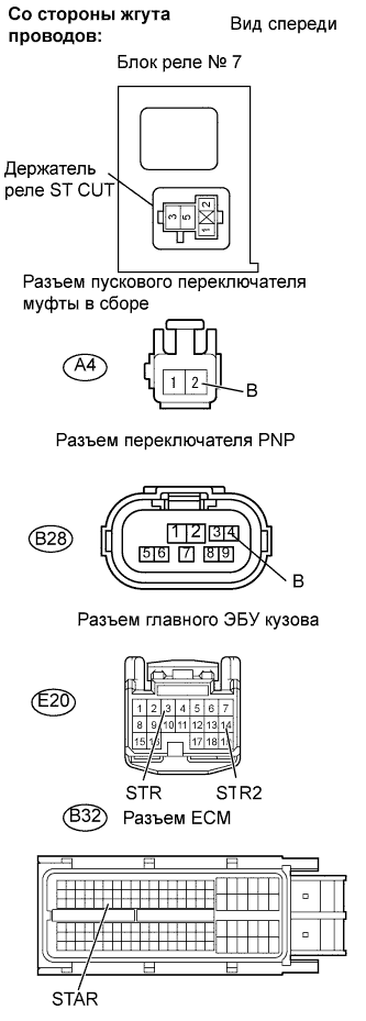
| 8.CHECK HARNESS AND CONNECTOR (ECM - CLUTCH START SWITCH OR PARK / NEUTRAL POSITION SWITCH ASSEMBLY - MAIN BODY ECU) |
Remove the ST CUT relay from the No. 7 relay block.
Disconnect the A4 clutch start switch assembly connector (for M/T models).
Disconnect the B28 PNP switch assembly connector (for A/T models).
Disconnect the E20 main body ECU connector.
Disconnect the B32 ECM connector.
Measure the resistance.
- Standard resistance (Check for open):
Tester Connection
| Specified Condition
|
ST CUT relay (3) - STAR (B32-52)
| Below 1 Ω
|
ST CUT relay (3) - STR2 (E20-14)
| Below 1 Ω
|
STR (E20-3) - ST CUT relay (5)
| Below 1 Ω
|
B (A4-2)*1 - ST CUT relay (5)
| Below 1 Ω
|
B (B28-4)*2 - ST CUT relay (5)
| Below 1 Ω
|
- УКАЗАНИЕ:
- *1: M/T
- *2: A/T
- Standard resistance (Check for short):
Tester Connection
| Specified Condition
|
ST CUT relay (3) - Body ground
| 10 kΩ or higher
|
ST CUT relay (5) - Body ground
| 10 kΩ or higher
|
Reconnect the ECM connector.
Reconnect the main body ECU connector.
Reconnect the clutch start switch assembly connector.
Reconnect the PNP switch assembly connector.
Reinstall the ST CUT relay.
| | REPAIR OR REPLACE HARNESS OR CONNECTOR |
|
|
| 9.INSPECT NO. 7 RELAY BLOCK (CHECK FOR SHORT) |
Disconnect the ECM connector.
Remove the ST CUT relay from the No. 7 relay block.
Measure the resistance between the terminals of the ST CUT relay holder.
- Standard resistance (Check for short):
Tester Connection
| Specified Condition
|
No. 7 Relay block ST CUT relay (3) - Body ground
| 10 kΩ or higher
|
No. 7 Relay block ST CUT relay (5) - Body ground
| 10 kΩ or higher
|
Reinstall the ST CUT relay.
Reconnect the ECM connector.
| | CHECK ENTRY AND START SYSTEM |
|
|
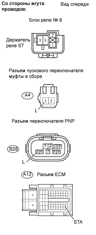
| 10.CHECK HARNESS AND CONNECTOR (CLUTCH START SWITCH OR PARK / NEUTRAL POSITION SWITCH ASSEMBLY - ECM - ST RELAY) |
Remove the ST relay from the No. 8 relay block.
Disconnect the A4 clutch start switch assembly connector (for M/T models).
Disconnect the B28 PNP switch assembly connector (for A/T models).
Disconnect the A12 ECM connector.
Measure the resistance.
- Standard resistance (Check for open):
Tester Connection
| Specified Condition
|
L (A4-1)*1 - STA (A12-48)
| Below 1 Ω
|
L (A4-1)*1 - ST relay (1)
| Below 1 Ω
|
L (B28-5)*2 - STA (A12-48)
| Below 1 Ω
|
L (B28-5)*2 - ST relay (1)
| Below 1 Ω
|
ST relay (2) - Body ground
| Below 1 Ω
|
- УКАЗАНИЕ:
- *1: M/T
- *2: A/T
- Standard resistance (Check for short):
Tester Connection
| Specified Condition
|
L (A4-1)*1 - Body ground
| 10 kΩ or higher
|
L (B28-5)*2 - Body ground
| 10 kΩ or higher
|
- УКАЗАНИЕ:
- *1: M/T
- *2: A/T
Reinstall the ST relay.
Reconnect the clutch start switch connector.
Reconnect the PNP switch assembly connector.
Reconnect the ECM connector.
| | REPAIR OR REPLACE HARNESS OR CONNECTOR |
|
|
Check that the battery is not depleted.
- OK:
- Battery is not depleted.
| 12.CHECK BATTERY TERMINAL |
Check that the battery terminals are not loose or corroded.
- OK:
- Battery terminals are not loose or corroded.
| | REPAIR OR REPLACE BATTERY TERMINAL |
|
|
| OK |
|
|
|
| CHECK AND REPLACE STARTER POWER SOURCE CIRCUIT |
|