READ VALUE OF INTELLIGENT TESTER (OUTPUT VOLTAGE OF HEATED OXYGEN SENSOR)
CHECK HARNESS AND CONNECTOR (CHECK FOR SHORT)
INSPECT HEATED OXYGEN SENSOR (CHECK FOR SHORT)
PERFORM CONFIRMATION DRIVING PATTERN
CHECK WHETHER DTC OUTPUT RECURS (DTC P0138)
READ VALUE OF INTELLIGENT TESTER (OUTPUT VOLTAGE OF HEATED OXYGEN SENSOR)
PERFORM CONFIRMATION DRIVING PATTERN
CHECK WHETHER DTC OUTPUT RECURS (DTC P0136)
PERFORM CONFIRMATION DRIVING PATTERN
CHECK WHETHER DTC OUTPUT RECURS (DTC P0136)
PERFORM ACTIVE TEST BY INTELLIGENT TESTER (INJECTION VOLUME)
INSPECT HEATED OXYGEN SENSOR (HEATER RESISTANCE)
INSPECT INTEGRATION RELAY (EFI MAIN RELAY)
CHECK HARNESS AND CONNECTOR (HEATED OXYGEN SENSOR - ECM)
DTC P0136 Oxygen Sensor Circuit Malfunction (Bank 1 Sensor 2) |
DTC P0137 Oxygen Sensor Circuit Low Voltage (Bank 1 Sensor 2) |
DTC P0138 Oxygen Sensor Circuit High Voltage (Bank 1 Sensor 2) |
DESCRIPTION
- УКАЗАНИЕ:
- Sensor 2 refers to the sensor mounted behind the Three-Way Catalytic Converter (TWC) and located far from the engine assembly.
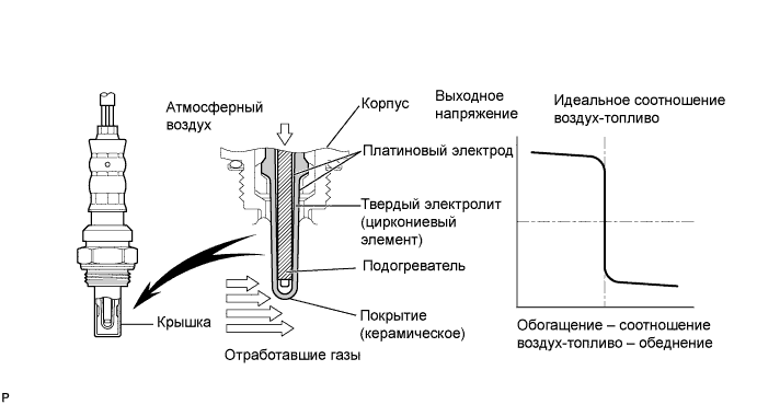
The HO2 sensor is located behind the TWC, and detects the oxygen concentration in the exhaust gas. Since the sensor is integrated with the heater that heats the sensing portion, it is possible to detect the oxygen concentration even when the intake air volume is low (the exhaust gas temperature is low).
When the air-fuel ratio becomes lean, the oxygen concentration in the exhaust gas is rich. The HO2 sensor informs the ECM that the post-TWC air-fuel ratio is lean (low voltage, i.e. less than 0.45 V).
Conversely, when the air-fuel ratio is richer than the stoichiometric air-fuel level, the oxygen concentration in the exhaust gas becomes lean. The HO2 sensor informs the ECM that the post-TWC air-fuel ratio is rich (high voltage, i.e. more than 0.45 V). The HO2 sensor has the property of changing its output voltage drastically when the air-fuel ratio is close to the stoichiometric level.
The ECM uses the supplementary information from the HO2 sensor to determine whether the air-fuel ratio after the TWC is rich or lean, and adjusts the fuel injection time accordingly. Thus, if the HO2 sensor is working improperly due to internal malfunctions, the ECM is unable to compensate for deviations in the primary air-fuel ratio control.
| DTC No. | DTC Detection Condition | Trouble Area |
| P0136 |
|
|
| P0137 |
|
|
| P0138 |
|
|
MONITOR DESCRIPTION
- Active Air-Fuel Ratio Control
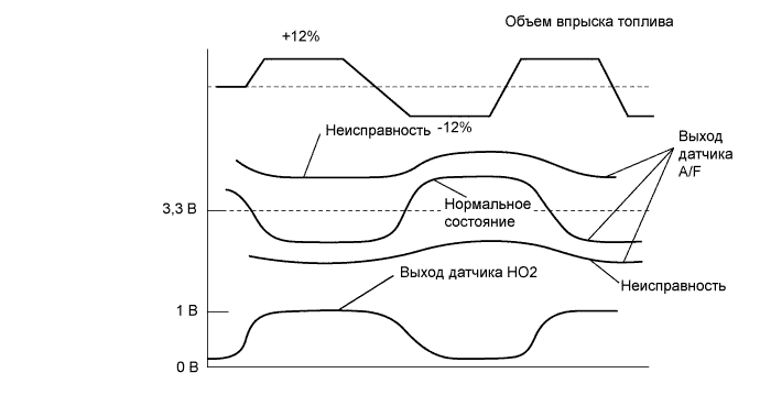
The ECM usually performs air-fuel ratio feedback control so that the Air-Fuel Ratio (A/F) sensor output indicates a near stoichiometric air-fuel level. This vehicle includes active air-fuel ratio control in addition to regular air-fuel ratio control. The ECM performs active air-fuel ratio control to detect any deterioration in the Three-Way Catalytic Converter (TWC) and Heated Oxygen (HO2) sensor malfunctions (refer to the diagram below).
Active air-fuel ratio control is performed for approximately 15 to 20 seconds while driving with a warm engine. During active air-fuel ratio control, the air-fuel ratio is forcibly regulated to become lean or rich by the ECM. If the ECM detects a malfunction, one of the following DTCs is set: DTC P0136 (abnormal voltage output), P0137 (open circuit) and P0138 (short circuit).
- Abnormal Voltage Output of HO2 Sensor (DTC P0136)
While the ECM is performing active air-fuel ratio control, the air-fuel ratio is forcibly regulated to become rich or lean. If the sensor is not functioning properly, the voltage output variation is small. For example, when the HO2 sensor voltage does not decrease to less than 0.21 V and does not increase to more than 0.59 V during active air-fuel ratio control, the ECM determines that the sensor voltage output is abnormal and sets DTC P0136.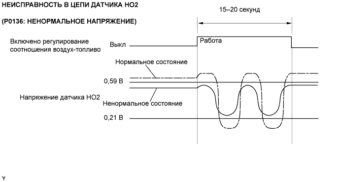
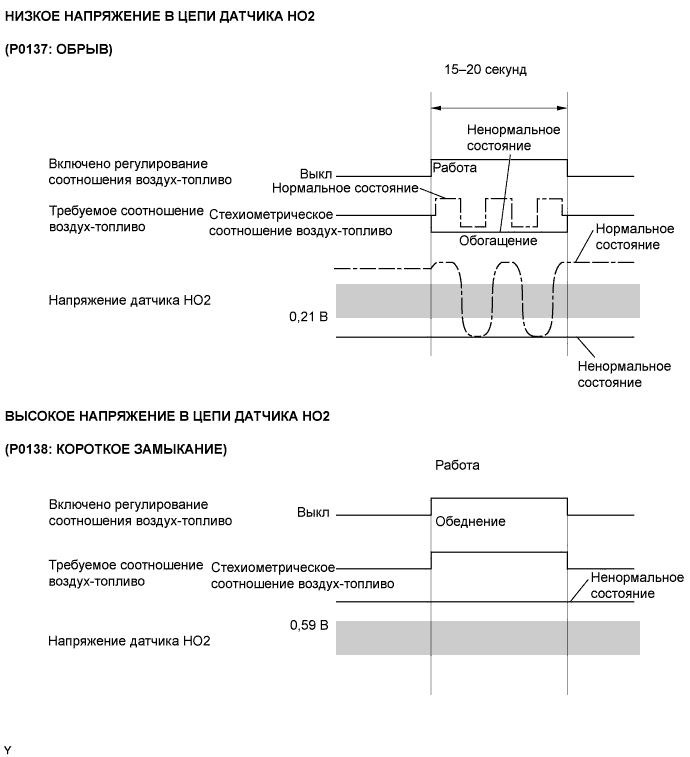
- Open or Short in Heated Oxygen (HO2) Sensor Circuit (DTC P0137 or P0138)
During active air-fuel ratio control, the ECM calculates the Oxygen Storage Capacity (OSC)* of the Three-Way Catalytic Converter (TWC) by forcibly regulating the air-fuel ratio to become rich or lean. If the HO2 sensor has an open or short, or the voltage output of the sensor decreases significantly, the OSC indicates an extraordinarily high value. Even if the ECM attempts to continue regulating the air-fuel ratio to become rich or lean, the HO2 sensor output does not change.
While performing active air-fuel ratio control, when the target air-fuel ratio is rich and the HO2 sensor voltage output is 0.21 V or less (lean), the ECM interprets this as an abnormally low sensor output voltage and sets DTC P0137. When the target air-fuel ratio is lean and the voltage output is 0.59 V or more (rich) during active air-fuel ratio control, the ECM determines that the sensor voltage output is abnormally high, and sets DTC P0138.- УКАЗАНИЕ:
- DTC P0138 is also set if the HO2 sensor voltage output is more than 1.2 V for 10 seconds or more.
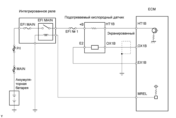
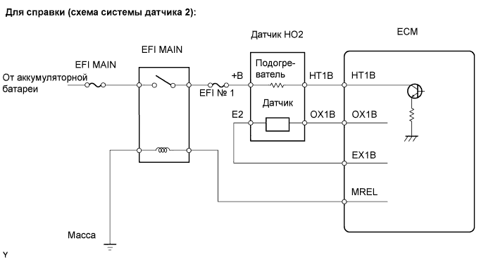
WIRING DIAGRAM
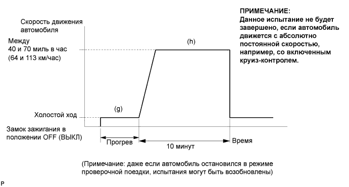
CONFIRMATION DRIVING PATTERN
- УКАЗАНИЕ:
- This confirmation driving pattern is used in the "PERFORM CONFIRMATION DRIVING PATTERN" procedure of the following diagnostic troubleshooting procedure.
- Performing this confirmation pattern will activate the Heated Oxygen (HO2) sensor monitor. (The catalyst monitor is performed simultaneously.) This is very useful for verifying the completion of a repair.
- (a) Connect the intelligent tester to the DLC3.
- (b) Turn the ignition switch on (IG).
- (c) Turn the tester ON.
- (d) Clear DTCs (if set) (see page RAV4_ACA30 RM000000PDK013X.html).
- (e) Enter Check Mode (see page RAV4_ACA30 RM000000PDL018X.html).
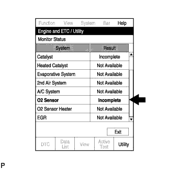
- (f) Select the following menu items: Powertrain / Engine and ECT / Utility.
- (g) Check that O2 Sensor is Incomplete.
- (h) Start the engine and warm it up.
- (i) Drive the vehicle at between 40 mph and 70 mph (64 km/h and 113 km/h) for at least 10 minutes.
- (j) Note the state of the Utility items. Those items will change to Complete as the O2 Sensor monitor operates.
- (k) On the tester, select the following menu items: Powertrain / Engine and ECT / DTC and check if any DTCs (any pending DTCs) are set.
- УКАЗАНИЕ:
- If O2 Sensor does not change to Complete, and any pending DTCs fail to set, extend the driving time.
INSPECTION PROCEDURE
- УКАЗАНИЕ:
- Intelligent tester only:
- Malfunctioning areas can be identified by performing the Control the Injection Volume for A/F Sensor function provided in the Active Test. The Control the Injection Volume for A/F Sensor function can help to determine whether the Air-Fuel Ratio (A/F) sensor, Heated Oxygen (HO2) sensor and other potential trouble areas are malfunctioning.
- The following instructions describe how to conduct the Control the Injection Volume for A/F Sensor operation using the intelligent tester.
- Connect the intelligent tester to the DLC3.
- Start the engine and turn the tester ON.
- Warm up the engine at an engine speed of 2,500 rpm for approximately 90 seconds.
- On the tester, select the following menu items: Powertrain / Engine and ECT / Active Test / Control the Injection Volume for A/F Sensor.
- Perform the Control the Injection Volume for A/F Sensor operation with the engine idling (press the Right or Left button to change the fuel injection volume).
- Monitor the voltage outputs of the A/F and HO2 sensors (AFS B1 S1 and O2S B1 S2) displayed on the tester.
- УКАЗАНИЕ:
- The Control the Injection Volume for A/F Sensor operation lowers the fuel injection volume by 12.5% or increases the injection volume by 25%.
- The sensors react in accordance with increases and decreases in the fuel injection volume.
- Standard:
Tester Display
(Sensor)Injection Volume Status Voltage AFS B1 S1
(A/F)+25% Rich Less than 3.0 -12.5% Lean More than 3.35 O2S B1 S2
(HO2)+25% Rich More than 0.5 -12.5% Lean Less than 0.4
- ПРИМЕЧАНИЕ:
- The A/F sensor has an output delay of a few seconds and the HO2 sensor has a maximum output delay of approximately 20 seconds.
| Case | A/F Sensor (Sensor 1) Output Voltage | HO2 Sensor (Sensor 2) Output Voltage | Main Suspected Trouble Area | ||
| 1 | Injection Volume +25% -12.5% |  | Injection Volume +25% -12.5% | | - |
| Output Voltage More than 3.35 V Less than 3.0 V |  | Output Voltage More than 0.5 V Less than 0.4 V |  | ||
| 2 | Injection Volume +25% -12.5% | | Injection Volume +25% -12.5% | |
|
| Output Voltage Almost no reaction |  | Output Voltage More than 0.5 V Less than 0.4 V | | ||
| 3 | Injection Volume +25% -12.5% | | Injection Volume +25% -12.5% | |
|
| Output Voltage More than 3.35 V Less than 3.0 V | | Output Voltage Almost no reaction | | ||
| 4 | Injection volume +25% -12.5% | | Injection Volume +25% -12.5% | |
|
| Output Voltage Almost no reaction | | Output Voltage Almost no reaction | | ||
- Following the Control the Injection Volume for A/F Sensor procedure enables technicians to check and graph the voltage outputs of both the A/F and HO2 sensors.
- To display the graph, select the following menu items on the tester: Powertrain / Engine and ECT / Active Test / Control the Injection Volume for A/F Sensor / Enter / View / AFS B1 S1 and O2S B1 S2.
- УКАЗАНИЕ:
- Read freeze frame data using the intelligent tester. Freeze frame data records the engine condition when malfunctions are detected. When troubleshooting, freeze frame data can help determine if the vehicle was moving or stationary, if the engine was warmed up or not, if the air-fuel ratio was lean or rich, and other data from the time the malfunction occurred.
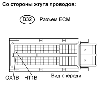
- If the OX1B wire from the ECM connector is short-circuited to the +B wire, DTC P0138 will be set.
| 1.READ OUTPUT DTC |
Connect the intelligent tester to the DLC3.
Turn the ignition switch on (IG) and turn the tester ON.
Select the following menu items: Powertrain / Engine and ECT / DTC.
Read DTCs.
- Result:
Display (DTC output) Proceed to P0138 A P0137 B P0136 C
|
| ||||
|
| ||||
| A | |
| 2.READ VALUE OF INTELLIGENT TESTER (OUTPUT VOLTAGE OF HEATED OXYGEN SENSOR) |
Connect the intelligent tester to the DLC3.
Turn the ignition switch on (IG) and turn the tester ON.
Select the following menu items: Powertrain / Engine and ECT / Data List / A/F Control System / O2S B1 S2.
Allow the engine to idle.
Read the Heated Oxygen (HO2) sensor output voltage while idling.
- Result:
HO2 Sensor Output Voltage Proceed to More than 1.2 V A Less than 1.0 V B
|
| ||||
| A | |
| 3.CHECK HARNESS AND CONNECTOR (CHECK FOR SHORT) |
 |
Turn the ignition switch off and wait for 5 minutes.
Disconnect the B32 ECM connector.
Measure the resistance.
- Standard:
Tester Connection Specified Condition HT1B (B32-47) - OX1B (B32-64) 10 kΩ or higher
Reconnect the ECM connector.
|
| ||||
| NG | |
| 4.INSPECT HEATED OXYGEN SENSOR (CHECK FOR SHORT) |
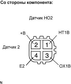 |
Disconnect the B19 HO2 sensor connector.
Measure the resistance.
- Standard:
Tester Connection Specified Condition +B (2) - E2 (4) 10 kΩ or higher +B (2) - OX1B (3) 10 kΩ or higher
Reconnect the HO2 sensor connector.
|
| ||||
| OK | ||
| ||
| 5.PERFORM CONFIRMATION DRIVING PATTERN |
| NEXT | |
| 6.CHECK WHETHER DTC OUTPUT RECURS (DTC P0138) |
On the intelligent tester, select the following menu items: Powertrain / Engine and ECT / DTC.
Read DTCs.
- Result:
Display (DTC Output) Proceed to P0138 A No output B
|
| ||||
| A | ||
| ||
| 7.READ VALUE OF INTELLIGENT TESTER (OUTPUT VOLTAGE OF HEATED OXYGEN SENSOR) |
Connect the intelligent tester to the DLC3.
Turn the ignition switch on (IG) and turn the tester ON.
Start the engine.
Select the following menu items: Powertrain / Engine and ECT / Data List / A/F Control System / O2S B1 S2
After warming up the engine, run the engine at an engine speed of 2,500 rpm for 3 minutes.
Read the output voltage of the HO2 sensor when the engine rpm is suddenly increased.
- УКАЗАНИЕ:
- Quickly accelerate the engine to 4,000 rpm 3 times using the accelerator pedal.
- Standard:
- Fluctuates between 0.4 V or less and 0.5 V or more.
|
| ||||
| OK | |
| 8.PERFORM CONFIRMATION DRIVING PATTERN |
| NEXT | |
| 9.CHECK WHETHER DTC OUTPUT RECURS (DTC P0136) |
On the intelligent tester, select the following menu items: Powertrain / Engine and ECT / DTC.
Read DTCs.
- Result:
Display (DTC Output) Proceed to P0136 A No output B
|
| ||||
| A | |
| 10.REPLACE HEATED OXYGEN SENSOR |
| NEXT | |
| 11.PERFORM CONFIRMATION DRIVING PATTERN |
| NEXT | |
| 12.CHECK WHETHER DTC OUTPUT RECURS (DTC P0136) |
On the intelligent tester, select the following menu items: Powertrain / Engine and ECT / DTC.
Read DTCs.
- Result:
Display (DTC Output) Proceed to P0136 A No output B
|
| ||||
| A | |
| 13.PERFORM ACTIVE TEST BY INTELLIGENT TESTER (INJECTION VOLUME) |
Connect the intelligent tester to the DLC3.
Start the engine and turn the tester ON.
Warm up the engine.
Select the following menu items: Powertrain / Engine and ECT / Active Test / Control the Injection Volume.
Change the fuel injection volume using the tester, monitoring the voltage output of Air-Fuel Ratio (A/F) and HO2 sensors displayed on the tester.
- УКАЗАНИЕ:
- Change the fuel injection volume within the range of -12% and +12%. The injection volume can be changed in 1% graduations within the range.
- The A/F sensor is displayed as AFS B1 S1, and the HO2 sensor is displayed as O2S B1 S2, on the intelligent tester.
- Result:
Tester Display (Sensor) Voltage Variation Proceed to AFS B1 S1 (A/F) Alternates between more and less than 3.3 V OK Remains at more than 3.3 V NG Remains at less than 3.3 V NG
- УКАЗАНИЕ:
- A normal HO2 sensor voltage (O2S B1 S2) reacts in accordance with increases and decreases in fuel injection volumes. When the A/F sensor voltage remains at either less or more than 3.3 V despite the HO2 sensor indicating a normal reaction, the A/F sensor is malfunctioning.
|
| ||||
| OK | ||
| ||
| 14.CHECK FOR EXHAUST GAS LEAKAGE |
- OK:
- No gas leakage.
|
| ||||
| OK | |
| 15.INSPECT HEATED OXYGEN SENSOR (HEATER RESISTANCE) |
|
Disconnect the B19 Heated Oxygen (HO2) sensor connector.
Measure the resistance of the HO2 sensor connector.
- Standard resistance:
Tester Connection Specified Condition HT1B (1) - +B (2) 11 to 16 Ω at 20°C (68°F) HT1B (1) - E2 (4) 10 kΩ or higher
Reconnect the HO2 sensor connector.
|
| ||||
| OK | |
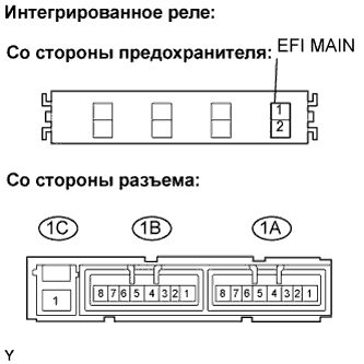
| 16.INSPECT INTEGRATION RELAY (EFI MAIN RELAY) |
Remove the integration relay from the engine room relay block.
Inspect the EFI MAIN fuse.
Remove the EFI MAIN fuse from the integration relay.
Measure the EFI MAIN fuse resistance.
- Standard resistance:
- Below 1 Ω
Reinstall the EFI MAIN fuse.
Inspect the EFI MAIN relay.
Measure the EFI MAIN relay resistance.
- Standard resistance:
Tester Connection Specified Condition 1C-1 - 1A-4 10 kΩ or higher Below 1 Ω
(Apply battery voltage between terminals 1A-2 and 1A-3)
Reinstall the integration relay.
|
| ||||
| OK | |
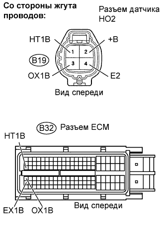
| 17.CHECK HARNESS AND CONNECTOR (HEATED OXYGEN SENSOR - ECM) |
  |
Disconnect the B19 HO2 sensor connector.
Turn the ignition switch on (IG).
Measure the voltage between the +B terminal of the HO2 sensor connector and body ground.
- Standard voltage:
Tester Connection Specified Condition +B (B19-2) - Body ground 9 to 14 V
Turn the ignition switch off.
Disconnect the B32 ECM connector.
Measure the resistance.
- Standard resistance (Check for open):
Tester Connection Specified Condition HT1B (B19-1) - HT1B (B32-47) Below 1 Ω OX1B (B19-3) - OX1B (B32-64) Below 1 Ω E2 (B19-4) - EX1B (B32-87) Below 1 Ω
- Standard resistance (Check for short):
Tester Connection Specified Condition HT1B (B19-1) or HT1B (B32-47) - Body ground 10 kΩ or higher OX1B (B19-3) or OX1B (B32-64) - Body ground 10 kΩ or higher E2 (B19-4) or EX1B (B32-87) - Body ground 10 kΩ or higher
Reconnect the HO2 sensor connector.
Reconnect the ECM connector.
|
| ||||
| OK | ||
| ||