Integration Relay -- On-Vehicle Inspection |
| 1. DISCONNECT CABLE FROM NEGATIVE BATTERY TERMINAL |
- ПРЕДОСТЕРЕЖЕНИЕ:
- Wait at least 90 seconds after disconnecting the cable from the negative (-) battery terminal to prevent airbag and seat belt pretensioner activation.
| 2. REMOVE INTEGRATION RELAY |
Remove the engine room No. 1 relay block cover.
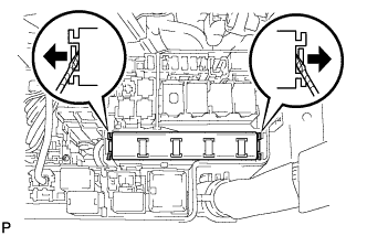
Using a screwdriver, detach the 2 claws and disconnect the integration relay from the engine room No. 1 junction block.
- УКАЗАНИЕ:
- Tape the screwdriver tip before use.
 |
Disconnect the 3 connectors from the integration relay.
| 3. INSPECT INTEGRATION RELAY |
- ПРИМЕЧАНИЕ:
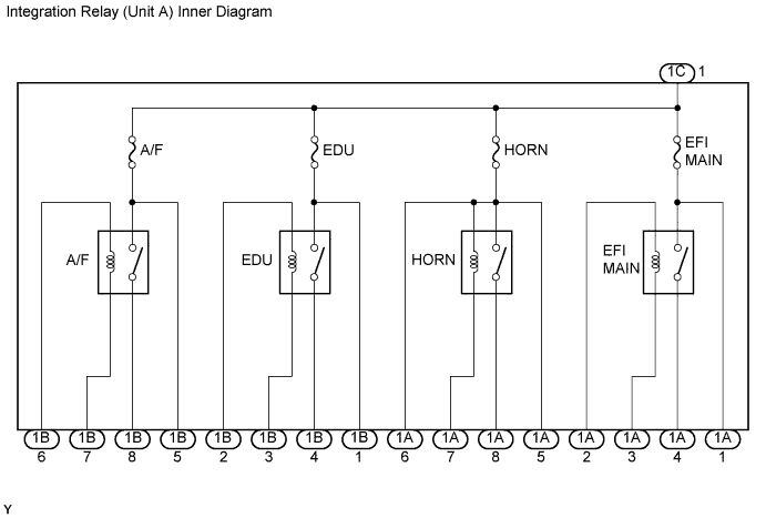
- Some relays are built into the integration relay (unit A). The integration relay cannot be disassembled. If there is a malfunction in the circuit of the integration relay, replace the integration relay.
- The internal circuit of the integration relay is as shown in the illustration. Inspect the integration relay using the following procedures.
Measure the resistance of the EFI MAIN relay.
Remove the EFI MAIN fuse. Measure the resistance between the terminals.
- Standard resistance:
Tester Connection Specified Condition 1A-2 - 1A-3 Below 1 Ω EFI MAIN fuse terminal 2 - 1A-4 10 kΩ or higher
Connect the battery's positive (+) lead to terminal 1A-2 and negative (-) lead to terminal 1A-3. Using an ohmmeter, check that there is resistance between the EFI MAIN fuse terminal 2 and terminal 1A-4 when battery voltage is applied between the terminals.
- Standard resistance:
Tester Connection Specified Condition EFI MAIN fuse terminal 2 - terminal 1A-4 Below 1 Ω
(when battery voltage is applied to terminals 1A-2 and 1A-3)
 |
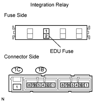
Measure the resistance of the EDU relay.
Remove the EDU fuse. Measure the resistance between the terminals.
- Standard resistance:
Tester Connection Specified Condition 1B-2 - 1B-3 Below 1 Ω EDU fuse terminal 2 - 1B-4 10 kΩ or higher
Connect the battery's positive (+) lead to terminal 1B-2 and negative (-) lead to terminal 1B-3. Using an ohmmeter, check that there is resistance between the EDU fuse terminal 2 and terminal 1B-4 when battery voltage is applied between the terminals.
- Standard resistance:
Tester Connection Specified Condition EDU fuse terminal 2 - terminal 1B-4 Below 1 Ω
(when battery voltage is applied to terminals 1B-2 and 1B-3)
 |
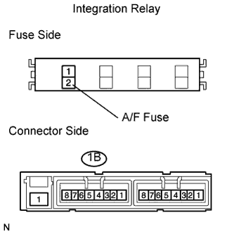
Measure the resistance of the A/F relay.
Remove the A/F fuse. Measure the resistance between the terminals.
- Standard resistance:
Tester Connection Specified Condition 1B-6 - 1B-7 Below 1 Ω A/F fuse terminal 2 - 1B-8 10 kΩ or higher
Connect the battery's positive (+) lead to terminal 1B-6 and negative (-) lead to terminal 1B-7. Using an ohmmeter, check that there is resistance between the A/F fuse terminal 2 and terminal 1B-8 when battery voltage is applied between the terminals.
- Standard resistance:
Tester Connection Specified Condition A/F fuse terminal 2 - terminal 1B-8 Below 1 Ω
(when battery voltage is applied to terminals 1B-6 and 1B-7)
 |
| 4. INSTALL INTEGRATION RELAY |
Connect the 3 connectors.
Attach the integration relay to the engine room junction block.
| 5. CONNECT CABLE TO NEGATIVE BATTERY TERMINAL |