DESCRIPTION
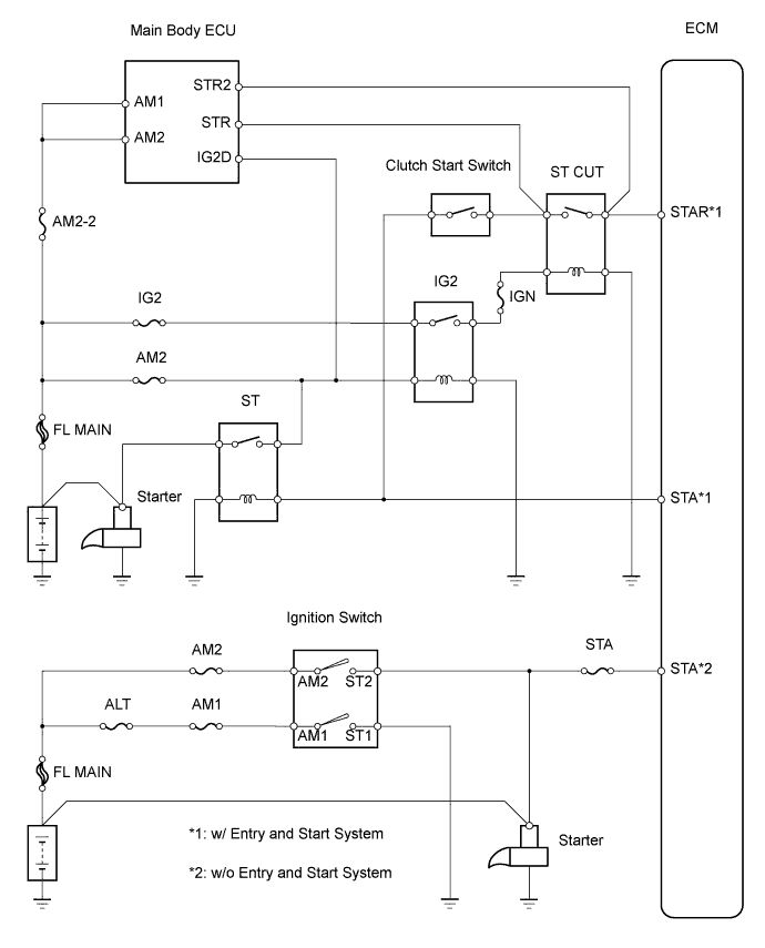
WIRING DIAGRAM
INSPECTION PROCEDURE
CHECK IF VEHICLE IS EQUIPPED WITH ENTRY AND START SYSTEM
READ VALUE OF INTELLIGENT TESTER (STARTER SIGNAL)
INSPECT IGNITION SWITCH ASSEMBLY
REPLACE IGNITION SWITCH ASSEMBLY
READ VALUE OF INTELLIGENT TESTER (STARTER SIGNAL)
REPAIR OR REPLACE HARNESS AND CONNECTOR (IGNITION SWITCH - STA TERMINAL OF ECM)
CHECK WHETHER DTC OUTPUT RECURS
READ VALUE OF INTELLIGENT TESTER (STARTER SIGNAL)
INSPECT CLUTCH START SWITCH
DTC P0617 Starter Relay Circuit High |
DESCRIPTION
While the engine is being cranked, positive battery voltage is applied to terminal STA of the ECM.If the ECM detects the starter control (STA) signal while the vehicle is being driven, it determines that there is a malfunction in the STA circuit. The ECM then illuminates the MIL and sets the DTC.This monitor runs when the vehicle has been driven at 20 km/h (12.4 mph) for more than 20 seconds.DTC No.
| DTC Detection Condition
| Trouble Area
|
P0617
| When conditions (a), (b) and (c) are met, positive (+B) battery voltage of 10.5 V or more applied to ECM for 20 seconds
(1 trip detection logic):
(a) Vehicle speed is more than 20 km/h (12.4 mph)
(b) Engine speed is more than 1,000 rpm
(c) STA signal is ON
| - Starter relay circuit
- Ignition switch
- ECM
|
WIRING DIAGRAM
INSPECTION PROCEDURE
- ПРИМЕЧАНИЕ:
- After replacing the ECM, the new ECM needs registration (see page RAV4_ACA30 RM000000TJ4007X.html) and initialization (see page RAV4_ACA30 RM000000TIN007X.html).
- УКАЗАНИЕ:
- The following troubleshooting process is based on the premise that the engine is cranked normally. If the engine will not crank, proceed to the problem symptoms table (see page RAV4_ACA30 RM000001WD2000X.html).
| 1.CHECK IF VEHICLE IS EQUIPPED WITH ENTRY AND START SYSTEM |
- Result:
Result
| Proceed to
|
w/o Entry and Start System
| A
|
w/ Entry and Start System
| B
|
| 2.READ VALUE OF INTELLIGENT TESTER (STARTER SIGNAL) |
Connect the intelligent tester to the DLC3.
Turn the ignition switch ON and turn the tester ON.
Enter the following menus: Powertrain / Engine and ECT / Data List / Starter Signal.
Check the value displayed on the tester when the ignition switch is turned to the on (IG) and Start positions.
- OK:
Ignition Switch Condition
| Tester Display (Starter Signal)
|
ON
| OFF
|
START
| ON
|
| | CHECK FOR INTERMITTENT PROBLEMS |
|
|
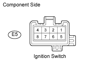
| 3.INSPECT IGNITION SWITCH ASSEMBLY |
Disconnect the E5 ignition switch connector.
Measure the resistance of the ignition switch.
- Standard resistance:
Condition
| Tester Condition
| Specified Condition
|
OFF
| Between all terminals
| 1 MΩ or more
|
ACC
| 2 - 3
| 1 Ω or less
|
ON
| 2 - 4, 6 - 7
| 1 Ω or less
|
START
| 1 - 2, 2 - 4, 6 - 7, 7 - 8
| 1 Ω or less
|
Reconnect the ignition switch connector.
| 4.REPLACE IGNITION SWITCH ASSEMBLY |
| 5.READ VALUE OF INTELLIGENT TESTER (STARTER SIGNAL) |
Connect the intelligent tester to the DLC3.
Turn the ignition switch ON and turn the tester ON.
Enter the following menus: Powertrain / Engine and ECT / Data List / Starter Signal.
Check the value displayed on the tester when the ignition switch is turned to the on (IG) and Start positions.
- OK:
Ignition Switch Condition
| Tester Display (Starter Signal)
|
ON
| OFF
|
START
| ON
|
| 6.REPAIR OR REPLACE HARNESS AND CONNECTOR (IGNITION SWITCH - STA TERMINAL OF ECM) |
| 7.CHECK WHETHER DTC OUTPUT RECURS |
Connect the intelligent tester to the DLC3.
Turn the ignition switch on (IG) and turn the tester ON.
Clear DTCs (see page RAV4_ACA30 RM000000PDK01FX.html).
Drive the vehicle at more than 12.4 mph (20 km/h) for over 20 seconds.
Enter the following menus: Powertrain / Engine and ECT / Data List / DTC.
Read DTCs.
- Result:
Display (DTC Output)
| Proceed to
|
P0617
| A
|
No DTC
| B
|
| 8.READ VALUE OF INTELLIGENT TESTER (STARTER SIGNAL) |
Connect the intelligent tester to the DLC3.
Turn the ignition switch on (IG) and turn the tester ON.
Enter the following menus: Powertrain / Engine and ECT / Data List / Starter Signal.
Check the value displayed on the tester when the ignition switch is turned to the on (IG) and Start positions.
- OK:
Ignition Switch Condition
| Tester Display (Starter Signal)
|
On (IG)
| OFF
|
Engine starts
| ON
|
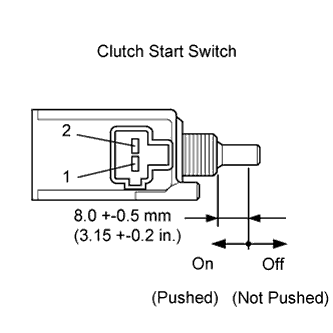
| 9.INSPECT CLUTCH START SWITCH |
Disconnect the A4 clutch start switch connector.
Measure the resistance when the clutch start switch is ON and OFF.
- Standard resistance:
Ignition Switch Position
| Tester Connection
| Specified Condition
|
On (pushed)
| 1 - 2
| Below 1 Ω
|
Off (not pushed)
| 1 - 2
| 10 kΩ or higher
|
Reconnect the clutch start switch connector.
| | REPLACE CLUTCH START SWITCH |
|
|
| OK |
|
|
|
| CHECK CRANKING HOLDING FUNCTION CIRCUIT |
|