DTC P0110 Intake Air Temperature Circuit
DTC P0112 Intake Air Temperature Circuit Low Input
DTC P0113 Intake Air Temperature Circuit High Input
Description
The intake air temperature sensor is built into the mass air flow meter and senses the intake air temperature.
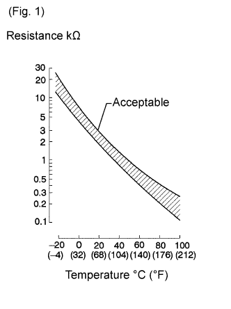
A thermistor built in the sensor changes its resistance value according to the intake air temperature.
The lower the intake air temperature, the greater the thermistor resistance value. The higher the intake air temperature, the lower the thermistor resistance value (see Fig. 1).
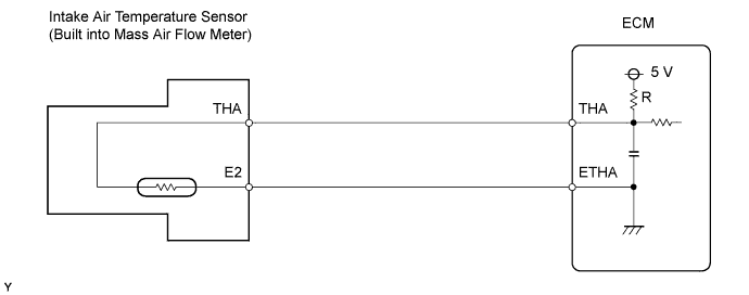
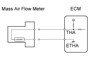
The intake air temperature sensor is connected to the ECM.
The 5 V power source voltage in the ECM is applied to the intake air temperature sensor from terminal THA via resistor R.
The resistor R and the intake air temperature sensor are connected in series. When the resistance value of the intake air temperature sensor changes in accordance with changes in the intake air temperature, the potential at terminal THA also changes. Based on this signal, the ECM increases the fuel injection volume to improve driveability with a cold engine.
Toyota fault code list P0110 P0112 P011
| DTC No. | DTC Detection Condition | Trouble Area |
| P0110 | Open or short in IAT sensor circuit for 0.5 seconds (1 trip detection logic) |
|
| P0112 | Short in IAT sensor circuit for 0.5 seconds (1 trip detection logic) |
|
| P0113 | Open in IAT sensor circuit for 0.5 seconds (1 trip detection logic) |
|
HINT:
When DTC P0110, P0112, or P0113 is detected, check the intake air temperature by entering the following menus on the intelligent tester: Powertrain / Engine and ECT / Data List / Intake Air.
| Temperature Displayed | Malfunction |
| -40°C (-40°F) | Open circuit |
| 140°C (284°F) or more | Short circuit |
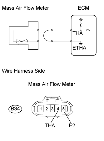
Wiring diagram
Inspection procedure
NOTICE:
After replacing the ECM, the new ECM needs registration and initialization.
HINT:
If DTCs relating to different systems are output, and they share terminal E2 as their ground, check this ground circuit first.
| 1.READ VALUE OF MASS AIR FLOW METER |
-
Connect the intelligent tester to the DLC3.
-
Turn the ignition switch on (IG) and turn the tester ON.
-
Enter the following menus: Powertrain / Engine and ECT / Data List / Intake Air.
-
Read the value.
Standard value:
Same value as the actual air temperature.
Result:Temperature Displayed Proceed to -40°C (-40°F) A 140°C (284°F) or more B OK (same as air temperature near intake manifold) C HINT:
- If there is an open circuit, the tester indicates -40°C (-40°F).
- If there is a short circuit, the tester indicates 140°C (284°F) or more.
|
|
||||
|
|
||||
| A | |
| 2.READ VALUE USING INTELLIGENT TESTER (CHECK FOR OPEN IN WIRE HARNESS) |
 |
-
Disconnect the B34 mass air flow meter connector.
-
Connect terminals THA and E2 of the mass air flow meter wire harness side connector.
-
Connect the intelligent tester to the DLC3.
-
Turn the ignition switch on (IG) and turn the tester ON.
-
Enter the following menus: Powertrain / Engine and ECT / Data List / Intake Air.
-
Read the value.
Standard value:
140°C (284°F) or more
-
Reconnect the mass air flow meter connector.
|
|
||||
| NG | |
| 3.CHECK WIRE HARNESS (MASS AIR FLOW METER - ECM) |
 |
-
Disconnect the B34 mass air flow meter connector.
-
Disconnect the B32 ECM connector.
-
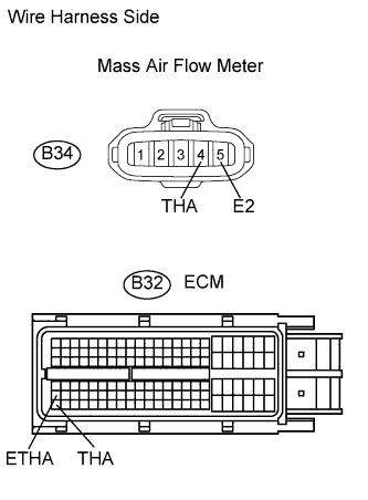
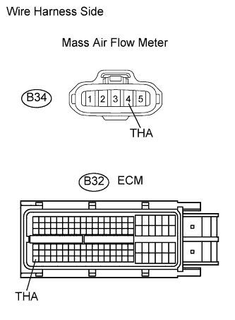
Measure the resistance of the wire harness side connectors.
Standard resistance:
Tester Connection Specified Condition B34-4 (THA) - B32-110 (THA) Below 1 ? B34-5 (E2) - B32-87 (ETHA) Below 1 ? -
Reconnect the mass air flow meter connector.
-
Reconnect the ECM connector.
|
|
||||
| NG | |
|
| 4.READ VALUE USING INTELLIGENT TESTER (CHECK FOR SHORT IN WIRE HARNESS) |
 |
-
Disconnect the B34 mass air flow meter connector.
-
Connect the intelligent tester to the DLC3.
-
Turn the ignition switch on (IG) and turn the tester ON.
-
Enter the following menus: Powertrain / Engine and ECT / Data List / Intake Air.
-
Read the value.
Standard value:
-40°C (-40°F)
-
Reconnect the mass air flow meter connector.
|
|
||||
| NG | |
| 5.CHECK WIRE HARNESS (MASS AIR FLOW METER - ECM) |
 |
-
Disconnect the B34 mass air flow meter connector.
-
Disconnect the B32 ECM connector.
-
Measure the resistance of the wire harness side connectors.
Standard resistance:
Tester Connection Specified Condition B34-4 (THA) or B32-110 (THA) - Body ground 10 k? or higher -
Reconnect the mass air flow meter connector.
-
Reconnect the ECM connector.
|
|
||||
| NG | |
|