Electric Steering Lock - Steering Lock Motor Drive Power Circuit
DESCRIPTION
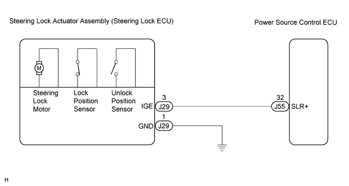
WIRING DIAGRAM
INSPECTION PROCEDURE
CHECK VEHICLE CONDITION
READ VALUE OF INTELLIGENT TESTER
INSPECT STEERING LOCK ACTUATOR ASSEMBLY (STEERING LOCK ECU)
CHECK HARNESS AND CONNECTOR (STEERING LOCK ACTUATOR ASSEMBLY - BODY GROUND)
CHECK HARNESS AND CONNECTOR (STEERING LOCK ACTUATOR ASSEMBLY - POWER SOURCE CONTROL ECU)
INSPECT STEERING LOCK ACTUATOR ASSEMBLY (STEERING LOCK ECU)
CHECK HARNESS AND CONNECTOR (STEERING LOCK ACTUATOR ASSEMBLY - POWER SOURCE CONTROL ECU)
ELECTRIC STEERING LOCK - Steering Lock Motor Drive Power Circuit
DESCRIPTION
The steering lock ECU is connected to the power source control ECU and certification ECU. The steering lock ECU cannot activate the motor unless it receives permission signals from both the ECUs. (The power source control ECU permits the steering lock ECU to supply power to activate the motor.)
WIRING DIAGRAM
INSPECTION PROCEDURE
| 1.CHECK VEHICLE CONDITION |
Check the problem symptom of the steering lock system.
- Result:
| Condition | Proceed to |
| Steering lock cannot be released | A |
| Steering cannot be locked | B |
| 2.READ VALUE OF INTELLIGENT TESTER |
Connect the intelligent tester to the DLC3.
Turn the engine switch on (IG), and turn the intelligent tester on.
Select the item below in the DATA LIST, and read its value displayed on the intelligent tester.
Entry & Start:| Item | Measurement Item / Range (Display) | Normal Condition |
| Lock/Unlock Receive | Steering lock command reception record/YES or NO | YES: Steering lock/unlock signal received
NO: Steering lock/unlock signal not received |
Check if steering unlock command reception is confirmed.
- OK:
- "YES" is displayed on the tester display.
| | CHECK ENTRY AND START SYSTEM |
|
|
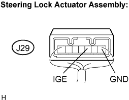
| 3.INSPECT STEERING LOCK ACTUATOR ASSEMBLY (STEERING LOCK ECU) |
Measure the voltage according to the value(s) in the table below.
- Standard voltage:
Tester connection
(Symbols) | Condition | Specified condition |
| J29-3 (IGE) - J29-1 (GND) | Engine switch off
Turn the engine switch on (ACC or IG)
| Motor activated: Below 1 V
Motor not activated:
10 to 12 V
|
| | PROCEED TO NEXT CIRCUIT INSPECTION SHOWN IN PROBLEM SYMPTOMS TABLE |
|
|
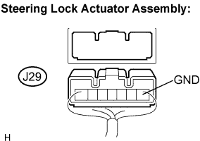
| 4.CHECK HARNESS AND CONNECTOR (STEERING LOCK ACTUATOR ASSEMBLY - BODY GROUND) |
Disconnect the J29 connector from the steering lock actuator assembly.
Measure the resistance according to the value(s) in the table below.
- Standard resistance:
Tester connection
(Symbols) | Condition | Specified condition |
| J29-1 (GND) - Body ground | Always | Below 1 Ω |
| | REPAIR OR REPLACE HARNESS OR CONNECTOR |
|
|
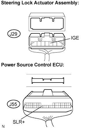
| 5.CHECK HARNESS AND CONNECTOR (STEERING LOCK ACTUATOR ASSEMBLY - POWER SOURCE CONTROL ECU) |
Disconnect the J55 connector from the power source control ECU.
Measure the resistance according to the value(s) in the table below.
- Standard resistance:
Tester connection
(Symbols) | Condition | Specified condition |
| J29-3 (IGE) - J55-32 (SLR+) | Always | Below 1 Ω |
| J29-3 (IGE) - Body ground | Always | 10 kΩ or higher |
| | REPAIR OR REPLACE HARNESS OR CONNECTOR |
|
|
| OK | |
| |
| REPLACE POWER SOURCE CONTROL ECU |
|
| 6.INSPECT STEERING LOCK ACTUATOR ASSEMBLY (STEERING LOCK ECU) |
Measure the voltage according to the value(s) in the table below.
- Standard voltage:
Tester connection
(Symbols) | Condition | Specified condition |
| J29-3 (IGE) - J29-1 (GND) | Specified condition is checked after performing the following:
Shift the shift lever to the P position
Turn the engine switch off
Open the driver's door
| Motor activated: Below 1 V
Motor not activated:
10 to 12 V
|
| | PROCEED TO NEXT CIRCUIT INSPECTION SHOWN IN PROBLEM SYMPTOMS TABLE |
|
|
| 7.CHECK HARNESS AND CONNECTOR (STEERING LOCK ACTUATOR ASSEMBLY - POWER SOURCE CONTROL ECU) |
Disconnect the J29 connector from the steering lock actuator assembly.
Disconnect the J55 connector from the power source control ECU.
Measure the resistance according to the value(s) in the table below.
- Standard resistance:
Tester connection
(Symbols) | Condition | Specified condition |
| J29-3 (IGE) - J55-32 (SLR+) | Always | Below 1 Ω |
| J29-3 (IGE) - Body ground | Always | 10 kΩ or higher |
| | REPAIR OR REPLACE HARNESS OR CONNECTOR |
|
|
| OK | |
| |
| REPLACE POWER SOURCE CONTROL ECU |
|