Dtc C1552 Pig Power Supply Voltage Malfunction
DESCRIPTION
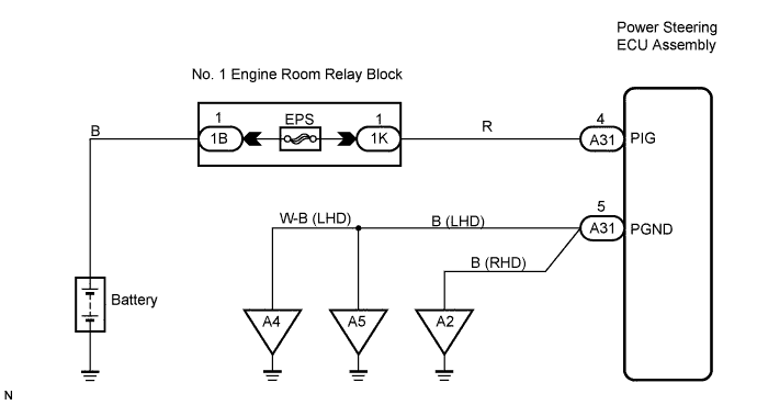
WIRING DIAGRAM
INSPECTION PROCEDURE
INSPECT FUSE (EPS FUSE)
CHECK HARNESS AND CONNECTOR (POWER STEERING ECU ASSEMBLY - BATTERY)
CHECK HARNESS AND CONNECTOR (POWER STEERING ECU ASSEMBLY - BODY GROUND)
DTC C1552 PIG Power Supply Voltage Malfunction
DESCRIPTION
This circuit supplies power to drive the power steering motor.
| DTC No. | DTC Detection Condition | Trouble Area |
| C1552 | This DTC is detected when power source voltage drops or remains high. | EPS fuse
Wire harness
Power steering ECU assembly
|
WIRING DIAGRAM
INSPECTION PROCEDURE
| 1.INSPECT FUSE (EPS FUSE) |
Remove the EPS fuse from the engine room relay block.
Check for continuity of the EPS fuses.
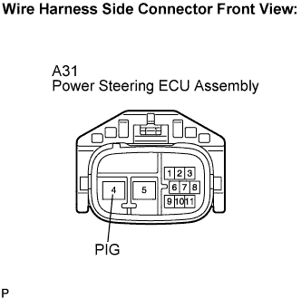
| 2.CHECK HARNESS AND CONNECTOR (POWER STEERING ECU ASSEMBLY - BATTERY) |
Disconnect the A31 connector from the power steering ECU assembly.
Measure the voltage according value(s) in the table below.
- Standard voltage:
| Tester Connection | Condition | Specified Condition |
| A31-4 (PIG) - Body ground | Always | 10 to 14 V |
| | REPAIR OR REPLACE HARNESS OR CONNECTOR |
|
|
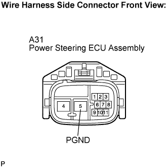
| 3.CHECK HARNESS AND CONNECTOR (POWER STEERING ECU ASSEMBLY - BODY GROUND) |
Measure the resistance according value(s) in the table below.
- Standard resistance:
| Tester Connection | Condition | Specified Condition |
| A31-5 (PGND) - Body ground | Always | Blow 1 Ω |
- If replacing the power steering ECU assembly, initialize the rotation angle sensor value and calibrate the torque sensor zero point .
| | REPAIR OR REPLACE HARNESS OR CONNECTOR |
|
|
| OK | |
| |
| REPLACE POWER STEERING ECU ASSEMBLY |
|